An emergency braking device for a hoist

A technology of emergency braking and braking device, which is applied in the direction of hoisting device, spring mechanism, etc., can solve the problems of inability to lock the gearbox, falling objects, hidden dangers, etc., and achieves a simple structure, avoids motor overload, and avoids accidents. Effect

Active Publication Date: 2021-10-29
SHENGZHOU YIYUAN INVESTMENT MANAGEMENT
View PDF11 Cites 0 Cited by
  • Summary
  • Abstract
  • Description
  • Claims
  • Application Information

AI Technical Summary

Problems solved by technology

Therefore, when the internal gear of the gearbox fails, the locking mechanism of the hoist cannot lock the gearbox, causing the reel to rotate, causing the lifting items to fall, which poses a safety hazard

Method used


Image

  • An emergency braking device for a hoist
  • An emergency braking device for a hoist
  • An emergency braking device for a hoist

Examples


Embodiment 1

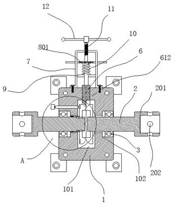
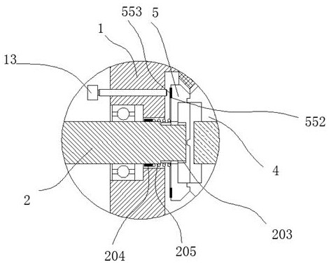
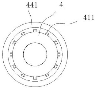
[0034]An emergency braking device for a hoist, comprising a box body 1, an inner cavity 101 is arranged inside the box body 1, and stepped holes 102 communicating with the inner cavity 101 are arranged on both sides of the box body 1, through which the The stepped hole 102 is equipped with a rotating shaft 2, and a bearing 3 is fitted between the rotating shaft 2 and the stepped hole 102. One end of the rotating shaft 2 is inserted into the inner cavity 101, and the other end is located outside the box body 1. The end of the rotating shaft 2 located outside the box body 1 is provided with a connecting sleeve 201, and the outside of the connecting sleeve 201 is processed with a threaded hole 202. The rotating shaft 2 on the right is processed with a fixed engagement disc 4, and the rotating shaft 2 on the left is processed with a fixed engagement disc 4. The rotating shaft 2 is equipped with a movable meshing disc 5; the inner side of the movable engaging disc 5 is annularly pro...

Embodiment 2

[0036] A frame 7 is arranged on the outside of the box body 1, a rod 8 is arranged on the outside of the insert plate 6, a force plate 801 is arranged on the end of the rod 8, and a force plate 801 is arranged on the inside of the frame 7. There is a cross plate 9, the rod 8 passes through the cross plate 9, a first spring 10 is sleeved on the rod 8, and the first spring 10 acts on the cross plate 9 and the cross plate 9. Between the force plates 801, the force plate 801 is pushed back at this time, the insert plate 6 is separated from the fixed engagement plate 4 and the movable engagement plate 5, and a threaded push plate is installed at the frame 7. rod 11 , the threaded push rod 11 is against the force plate 801 , and a plurality of handles 12 are arranged at the end of the threaded push rod 11 . In the above-mentioned structure, the main purpose is to push the inserting plate in safely, and the threaded push rod 11 is used, which makes the operation more convenient. Whe...

Embodiment 3

[0038] The width of the stress plate 801 is greater than the width of the frame 7, and the two sides of the stress plate 801 are provided with a first retreat groove 881 that retreats from the frame 7, and the two ends of the force plate 801 Extend to the outside of the frame 7; in the above structure, the width of the force plate 801 is relatively large, so when we encounter an emergency, we can first manually press the force plate 801, first cut off the power input of the motor, Then screw in threaded push rod 11 by a workman and lock.


PUM


Abstract

The invention discloses an emergency brake device for a hoist, which comprises a box body, an inner cavity is arranged inside the box body, and stepped holes communicating with the inner cavity are arranged on both sides of the box body, through the step The hole is equipped with a rotating shaft, and a bearing is matched between the rotating shaft and the stepped hole. One end of the rotating shaft is inserted into the inner cavity, and the other end is located outside the box body. The end of the rotating shaft located outside the box body A connecting sleeve is provided, and the outside of the connecting sleeve is processed with a threaded hole, a fixed engaging disc is processed on the right rotating shaft, and a movable engaging disc is matched on the left rotating shaft; the structure of this product is relatively simple, and the cost is low. Relatively cheap, suitable for promotional use.

Description

technical field [0001] The invention relates to an emergency brake device for a hoist. Background technique [0002] Hoist, also known as winch, is a light and small lifting device that uses a reel to wind a wire rope or chain to lift or pull heavy objects. The hoist can lift heavy objects vertically, horizontally or obliquely. The hoist is divided into two types: manual hoist and electric hoist. Now mainly electric hoist. It can be used alone or as a component in machinery such as lifting, road building and mine hoisting. It is widely used because of its simple operation, large amount of rope winding and convenient displacement. It is mainly used for material lifting or flat dragging in construction, water conservancy projects, forestry, mines, docks, etc. [0003] The hoist outputs power through the motor, changes the transmission ratio through the gearbox, and then drives the reel to rotate. In the prior art, a locking mechanism is installed between the motor and the...

Claims


Application Information

Patent Timeline
Patent Type & Authority Patents(China)
IPC IPC(8): B66D1/54B66D5/32
CPCB66D1/54B66D5/32
Inventor 袁乐天甄益权
Owner SHENGZHOU YIYUAN INVESTMENT MANAGEMENT
Why Eureka
Try Eureka