Self-adaptive skin traction system

An adaptive, skin-based technology, applied in the field of medical devices, can solve problems such as obstruction of blood flow, poor growth, damage, etc., and achieve the effect of improving the adjustment range, simple components, and easy manufacturing

Inactive Publication Date: 2020-10-02
魏姝玥
View PDF12 Cites 0 Cited by
  • Summary
  • Abstract
  • Description
  • Claims
  • Application Information

AI Technical Summary

Benefits of technology

This invention simplifies how an electrode has been designed that allows multiple areas on its surface to move freely with greater precision than other parts of the apparatus. Additionally, this technology makes it easier to use while still being effective at creating strong electrical contact between the patient's skin and the equipment they were applying treatment or examination during surgery.

Problems solved by technology

Technication describes two types of retraction systems used after severe accidents like injury. One system includes an eyelet made up of multiple anchoring point locations along the edges of the incision site where the damaged area has stopped growing until healing naturally takes place again. A special device called a suture thread looper applies pressure onto each location while keeping them fixed together. By controllably stretching these areas overall, the amount of stress applied to the surrounding soft body parts should decrease smoothly when trying to recover without causing damage.

Method used


Image

  • Self-adaptive skin traction system
  • Self-adaptive skin traction system
  • Self-adaptive skin traction system

Examples


Embodiment Construction

[0065] The present invention will be further described below in conjunction with embodiment.

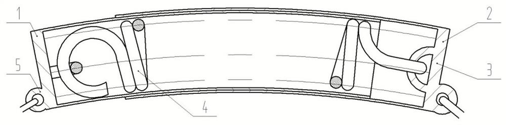
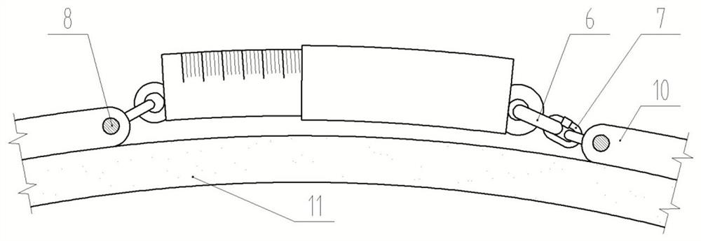
[0066] Such as Figure 1-4 As shown, an adaptive skin stretching system according to the present application is characterized in that: comprising,

[0067] at least one pull force indicator,

[0068] The pulling force display part includes a flexible inner cylinder 1,

[0069] A flexible outer cylinder 2 socketed outside the flexible inner cylinder;

[0070] Slidable fit between flexible inner cylinder and flexible outer cylinder;

[0071] Both the inner and outer cylinders have end caps 3, and springs 4 are connected inside the two end caps;

[0072] Scales are drawn on the outside of the flexible inner cylinder or on the flexible outer cylinder to show the sliding distance when they slide relative to each other;

[0073] When the spring is at the initial length, the displayed scale is scale 0;

[0074] There are connecting parts 5 on the outer sides of the two end covers 3; ...


PUM


Abstract

The invention provides a self-adaptive skin traction system. The self-adaptive skin traction system is characterized by comprising at least one traction force display part, at least one tension adjusting part and a traction needle, wherein each traction force display part comprises a flexible inner cylinder and a flexible outer cylinder connected to the outer portion of the flexible inner cylinderin a sleeving mode; the flexible inner cylinder is in sliding fit with the flexible outer cylinder; the inner cylinder and the outer cylinder are provided with end covers, and springs are connected into the two end covers; scales are drawn outside the flexible inner cylinder or on the flexible outer cylinder, so that the sliding distance can be displayed when the flexible inner cylinder and the flexible outer cylinder slide relatively; when the spring is in the initial length, the displayed scale is a scale point 0; connecting parts are arranged on the outer sides of the two end covers; the at least one tension adjusting part is connected with the traction force display part; and the traction needle penetrates into the pulled skin, and a bridge-shaped arched hanging part connected with the traction force display part or the tension adjusting part is arranged on the needle.

Description


Claims


Application Information

Patent Timeline
Owner 魏姝玥
Why Eureka
Try Eureka