Walking aid device for orthopedic nervous system rehabilitation

A neurological and orthopedic technology, applied in the field of medical assistance, can solve the problems of low safety performance, poor comfort, and single structure of the walking aid device, and achieve the effects of high practical performance, reducing fatigue, and improving safety.

Inactive Publication Date: 2020-10-02
陶桂芳
View PDF0 Cites 0 Cited by
  • Summary
  • Abstract
  • Description
  • Claims
  • Application Information

AI Technical Summary

Problems solved by technology

[0004] 1. The structure of the walking aid device is very simple, which cannot meet the patient's action requirements, and the steering needs assistance from others, and the practical performance is poor;
[0005] 2. The walking aid device adopts the structure of rollers for walking, or adopts the form of a bracket, which needs to be manually applied by the patient. After a long time of use, the patient is prone to fatigue, poor comfort, and low safety performance, which is not conducive to the recovery of the patient.

Method used


Image

  • Walking aid device for orthopedic nervous system rehabilitation
  • Walking aid device for orthopedic nervous system rehabilitation
  • Walking aid device for orthopedic nervous system rehabilitation

Examples


Embodiment 1

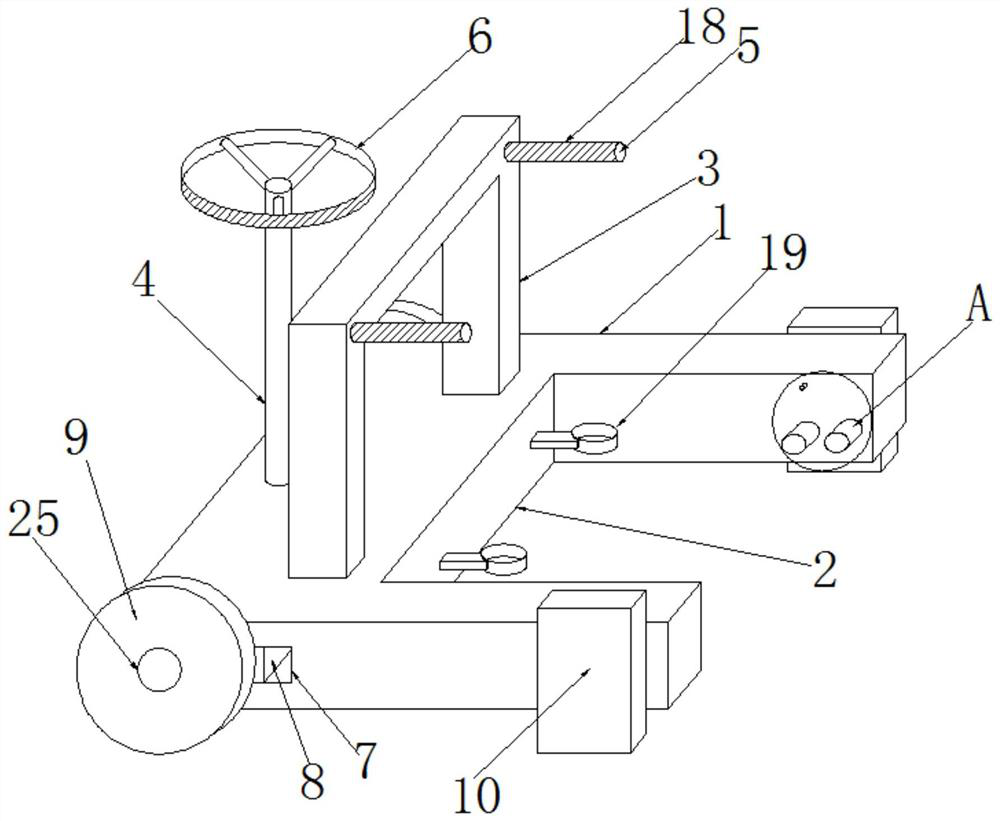
[0042] Embodiment one, such as figure 1 As shown, a walking aid for orthopedic nervous system rehabilitation according to an embodiment of the present invention includes a base 1, a groove 2 is provided on one side of the base 1, a support frame 3 is provided on the upper end of the base 1, and a support frame 3 is provided. One side and the upper end of the base 1 is provided with a rotating rod 4, the other side of the upper end of the support frame 3 is provided with two sets of handles 5, the upper end of the rotating rod 4 is provided with an adjusting disc 6, and the inner side of the base 1 is provided with a through groove 7 , the inside of the through groove 7 is provided with a steering mechanism 8, and both ends of the steering mechanism 8 and both sides of the base 1 are provided with rollers 9, and one end of the base 1 and both sides of the groove 2 are provided with a driving device 10.

[0043] By setting the steering mechanism 8, the direction can be adjusted...

Embodiment 2

[0044] Embodiment two, such as Figure 4 As shown, on the basis of Embodiment 1, the present invention provides a technical solution: two sets of fixing rings 19 are arranged on the inner side of the groove 2, and springs 20 are arranged on both sides of the fixing rings 19, and the springs 20 are far away from the fixing rings. One end of the ring 19 is connected to the groove 2 , and one end of the two sets of fixing rings 19 is fixed by Velcro 21 , and the interior of the fixing rings 19 is filled with a sponge 22 .

[0045] By arranging two sets of fixing rings 19, the patient's legs can be placed inside the fixing rings 19, so that the fixing rings 19 can drive the movement of the patient's legs without the need for the patient's legs to move by themselves. By setting the spring 20, it plays a role of buffering , the opening and closing of the fixed ring 19 is facilitated by the Velcro 21, so that the fixed ring 19 is convenient to disassemble, and the inside of the fixed r...

Embodiment 3

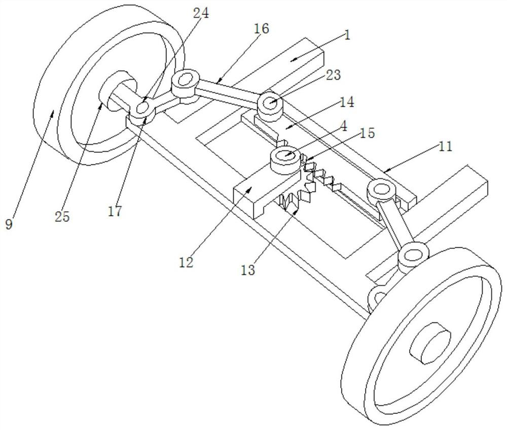
[0046] Embodiment three, such as Figure 1-3 As shown, on the basis of Embodiment 1 and Embodiment 2, the present invention provides a technical solution: the steering mechanism 8 includes a fixed rod 11, the fixed rod 11 is located on the base 1, and one side of the fixed rod 11 is located on the side of the base 1 The upper end is provided with a fixed mount 12, and the fixed mount 12 is an L-shaped structure, the lower end of the rotating rod 4 is inserted into one end of the fixed mount 12, and one end of the rotating rod 4 is provided with a gear 13 at the lower end of the fixed mount 12, and the fixed rod 11 The upper end of movable rod one 14 is provided with, and one side of movable rod one 14 is provided with the rack 15 that matches with gear 13, and the two ends of movable rod one 14 are all movably connected with an end of movable rod two 16, and movable rod two 16 An end far away from movable rod one 14 is connected with an end of movable rod three 17, and movable...


PUM


Abstract

The invention discloses a walking aid device for orthopedic nervous system rehabilitation. The walking aid device comprises a base, wherein a groove is formed in one side of the base, a support frameis arranged at an upper end of the base, a rotating rod is arranged on one side of the support frame and located at the upper end of the base, two groups of handles are arranged on the other side of an upper end of the support frame, an adjusting disc is arranged at an upper end of the rotating rod, a through groove is formed in one side of interior of the base, a steering mechanism is arranged inthe through groove, both ends of a steering mechanism and on both sides of the base are provided with rollers, a driving device is arranged at one end of the base and at two sides of the groove, wherein the steering mechanism comprises a fixing rod, the fixing rod is arranged on the base, a fixing frame is arranged at one side of the fixing rod and at the upper end of the base, the fixing frame is of an L-shaped structure, a lower end of the rotating rod is inserted into one end of the fixing frame in a penetrating mode, a gear is arranged at one end of the rotating rod and at a lower end ofthe fixing frame, a first movable rod is arranged at the upper end of the fixing rod, and one side of the first movable rod is provided with a rack matched with a gear.

Description

technical field [0001] The invention relates to the field of medical assistance, in particular to a walking aid for orthopedic nervous system rehabilitation. Background technique [0002] At present, the Department of Orthopedics is one of the most common departments in major hospitals. It mainly studies the anatomy, physiology and pathology of the musculoskeletal system, and uses drugs, surgery and physical methods to maintain and develop the normal form and function of this system. Trauma caused by traffic accidents has increased significantly, some patients have inconvenience in daily walking, and dangerous accidents may occur if they are not careful, so walking aids are needed to assist walking. [0003] At present, some existing walking aid structures have the following problems: [0004] 1. The structure of the walking aid device is very simple, which cannot meet the patient's action requirements, and the steering needs assistance from others, and the practical perfor...

Claims


Application Information

Patent Timeline
Patent Type & Authority Applications(China)
IPC IPC(8): A61H3/04
CPCA61H3/04A61H2003/007A61H2003/043
Inventor 不公告发明人
Owner 陶桂芳
Why Eureka
Try Eureka