
A wearable hearing aid

A hearing aid and wearable technology, applied in the directions of hearing aids, hearing aid shells, hearing aid installation/interconnection, etc., can solve the problems of large space and access box, inconvenient portability, prominent structure, etc., and achieve volume reduction and avoid inconvenience in carrying. Bump damage, avoid injury effect

Active Publication Date: 2021-12-24
陈虎
View PDF26 Cites 0 Cited by
  • Summary
  • Abstract
  • Description
  • Claims
  • Application Information

AI Technical Summary

Problems solved by technology

[0003] Wearable hearing aids currently on the market are bone conduction hearing aids and glasses-type hearing aids, which can be worn directly. There is a certain curvature, and it is easy to be crushed when placed, resulting in property loss, and the structure of the wearable hearing aid is fixed, the required space and access box are larger, and it is easy to cause inconvenient portability and bump damage when not in use

Method used


Image

  • A wearable hearing aid
  • A wearable hearing aid
  • A wearable hearing aid

Examples


Embodiment 1

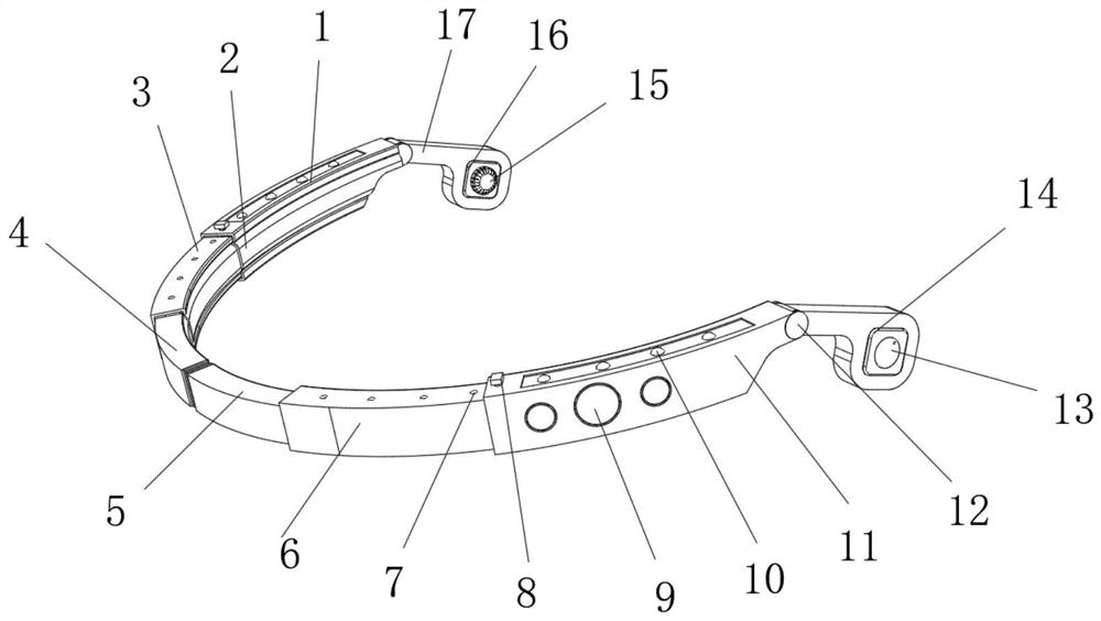
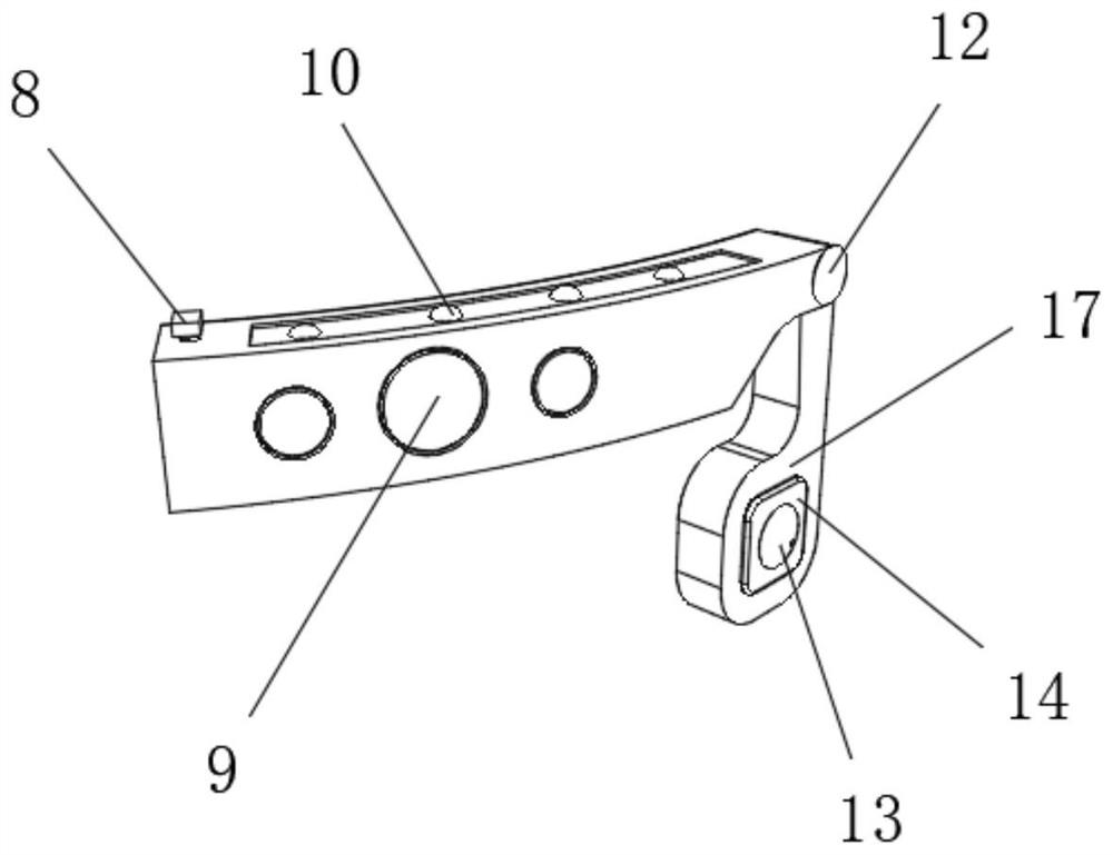
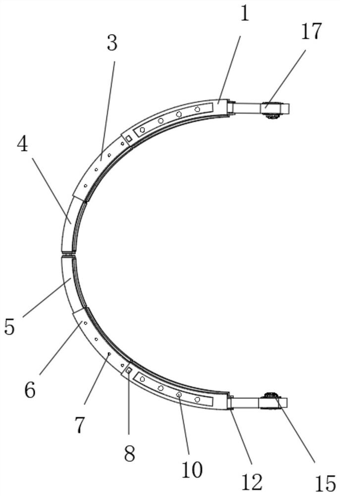
[0030] refer to Figure 1-5 , a wearable hearing aid, comprising a right sleeve rod 1 and a left sleeve rod 11, the outer wall of one side of the right sleeve rod 1 is provided with a first rectangular groove, and the inner wall of the first rectangular groove is slidably connected with a first right Telescopic rod 3, one side outer wall of the first right telescopic rod 3 is provided with a second rectangular groove, and the inner wall of the second rectangular groove is slidably connected with a second right telescopic rod 4, and one side of the second right telescopic rod 4 The outer wall is connected with the right magnetic strip 20 by screws, the outer wall of one side of the left cover rod 11 is provided with a third rectangular groove, and the inner wall of the third rectangular groove is slidably connected with the first left telescopic rod 6, the first left telescopic rod 6 A fourth rectangular groove is provided on one side of the outer wall, and the inner wall of th...

Embodiment 2

[0038] refer to Figure 1-3 , a wearable hearing aid. Compared with Embodiment 1, this embodiment also includes a sixth rectangular groove on the top outer wall of the left sleeve rod 11 and the right sleeve rod 1, and the inner wall of the sixth rectangular groove Both are connected with LED light bars 10 by screws, and the top outer wall of the LED light bars 10 is connected with a shield by screws, and the shields are connected with the left sleeve rod 11 and the right sleeve rod 1 .

[0039] Working principle: When the wearable hearing aid is out of order and cannot be used, or the line of sight is not good, the switch of the LED light bar 10 is turned on through the control button 9, and the LED light is on to attract people's attention, and the warning process of the wearable hearing aid is completed.


PUM


Abstract

The invention discloses a wearable hearing aid, which comprises a right sleeve rod and a left sleeve rod, the outer wall of one side of the right sleeve rod is provided with a first rectangular groove, and the inner wall of the first rectangular groove is slidably connected with a second A right telescopic rod, the outer wall of one side of the first right telescopic rod is provided with a second rectangular groove, and the inner wall of the second rectangular groove is slidably connected with a second right telescopic rod, and one side of the second right telescopic rod The outer wall is connected with the right magnetic strip by screws, the outer wall of one side of the left sleeve rod is provided with a third rectangular groove, and the inner wall of the third rectangular groove is slidably connected with the first left telescopic rod. The spherical magnet of the present invention departs from the circular groove, the telescopic rod slides into the sleeve rod, and the rotating shaft puts away the behind-the-ear earphone, completing the storage of the wearable earphone, so that the hearing aid is not easy to be crushed and causes property loss when placed, and the hearing aid The shrinkage volume is reduced to avoid the phenomenon of inconvenient carrying, bumping and damage when not in use.

Description

technical field [0001] The invention relates to the technical field of hearing aids, in particular to a wearable hearing aid. Background technique [0002] A hearing aid is a small loudspeaker that amplifies the originally inaudible sound, and then uses the residual hearing of the hearing-impaired to send the sound to the auditory center of the brain so that the sound can be felt. The types of hearing aids can be divided into: box type, behind-the-ear type, and in-ear type from the external structure, and the in-ear type can be divided into ordinary in-ear type, ear canal type, and deep ear canal type; from the electronic principle can be divided into: analog hearing aids ; Programmable hearing aids, full digital hearing aids, wide dynamic language technology hearing aids, etc.; divided into air conduction hearing aids and bone conduction hearing aids according to the conduction method. Cassette, behind-the-ear, and in-ear are all air conduction hearing aids. [0003] Wear...

Claims


Application Information

Patent Timeline
Patent Type & Authority Patents(China)
IPC IPC(8): H04R25/00
CPCH04R25/65H04R25/60H04R2225/00H04R2460/13
Inventor 陈虎陈媛
Owner 陈虎
Learn More