Illuminating device for sorting machine or inspecting machine

A lighting device and inspection machine technology, which is applied in the field of color sorting machines, can solve the problems of unclear detection images and failure to illuminate a part of grains, etc., and achieve the effects of miniaturization, quantity reduction, and envelope size reduction

Inactive Publication Date: 2020-10-02
SATAKE CORP
View PDF9 Cites 0 Cited by
  • Summary
  • Abstract
  • Description
  • Claims
  • Application Information

AI Technical Summary

Problems solved by technology

Whenever the grain is photographed, the trajectory of the grain flowing down is predicted in advance, and the lighting device is arranged so that the light hits the object surface of the grain. When part of the grain cannot be illuminated, an unclear inspection image will be generated

Method used


Image

  • Illuminating device for sorting machine or inspecting machine
  • Illuminating device for sorting machine or inspecting machine
  • Illuminating device for sorting machine or inspecting machine

Examples


no. 1 approach >

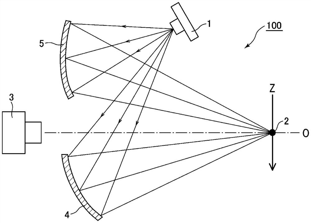
[0042] The illumination light source applied to the illumination device of this embodiment is configured by arranging one row or a plurality of LED chips on a substrate according to the width of the slide rail. LEDs can also exist in multiple colors mixed. In addition, in other embodiments, light emitters other than LED chips may also be used.

[0043] In addition, the plurality of reflectors used in this embodiment are concave mirrors, and an elliptical concave mirror having an elliptical curvature is used. In addition, the concave curved surface does not necessarily have to have an elliptical curvature, and may be a concave surface having a parabolic or hyperbolic curvature when it is desired to weaken the light-gathering characteristic of the object to be detected. Furthermore, it may be a free-form surface capable of freely setting the incident angle, light-condensing position, and light-condensing degree of light toward the object to be detected.

[0044] figure 1 It ...

no. 2 approach >

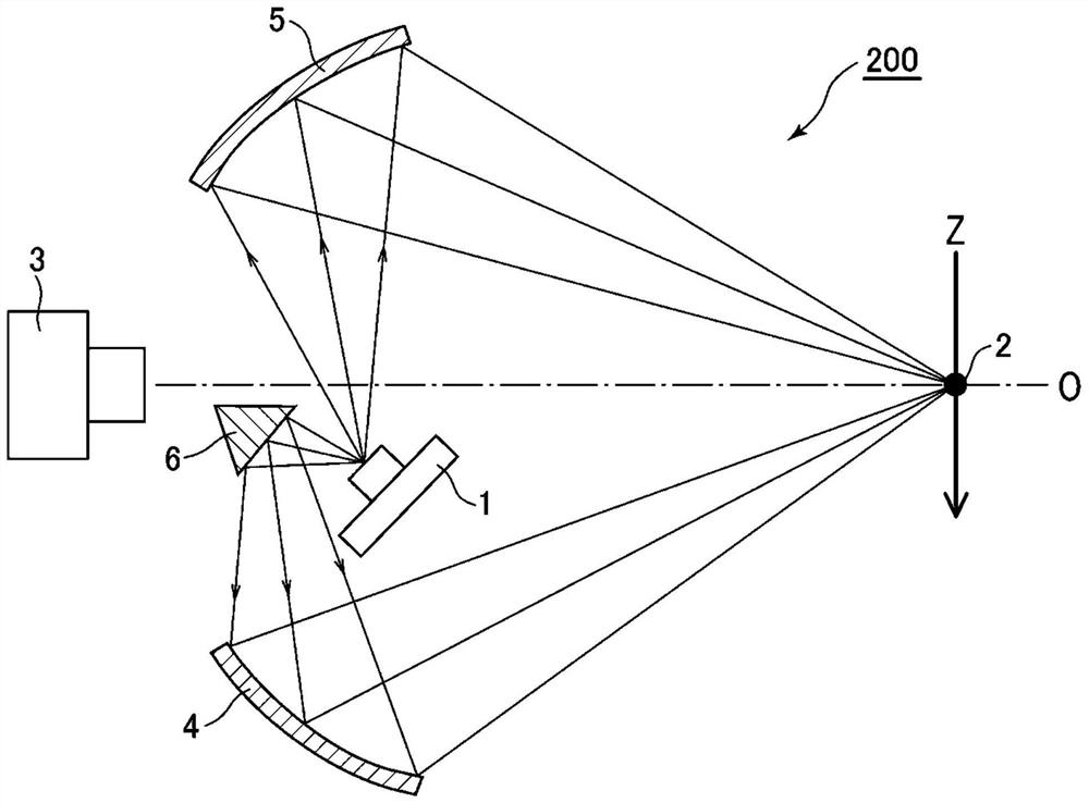
[0051] Such as figure 2 As shown, the lighting device 200 of the second embodiment further includes a refracting mirror 6 . The functions of other constituent elements are the same as those of the first embodiment, and therefore description thereof will be omitted.

[0052] The refracting mirror 6 of the present embodiment is a plane mirror, and is used to bend the optical path of the light emitted from the illumination light source 1 to make the light reach the first reflector 4 . Therefore, unlike the configuration in the first embodiment, as figure 2 As shown, the illumination light source 1 is arranged between the first reflector 4 and the second reflector 5, and the first reflector 4 (for example, an elliptical concave mirror) and the second reflector 5 are arranged to face each other. As shown in the figure, the light group from the illumination source 1 is not directly incident on the first reflector 4, but it is assumed that a part of the light group from the illum...

no. 3 approach >

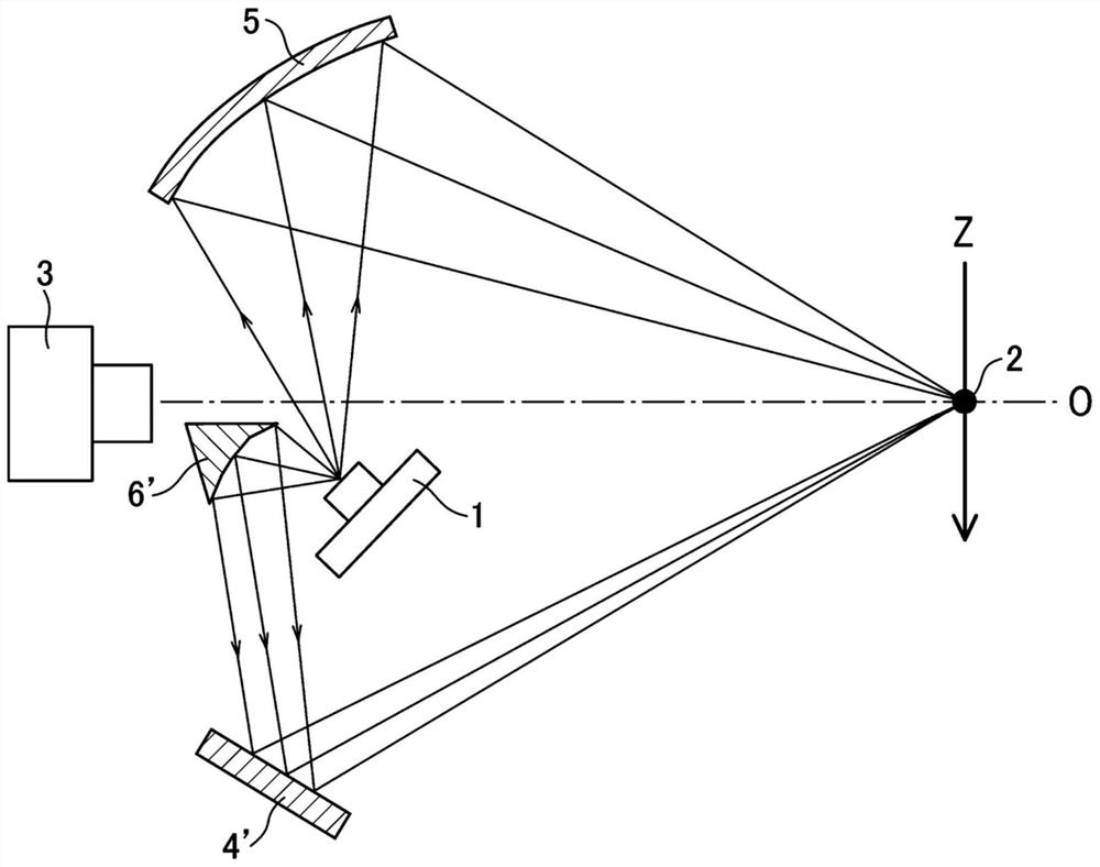
[0060] Such as Figure 4 As shown, the lighting device 300 of the third embodiment is characterized in that the refracting mirror 6 has a plurality of reflecting surfaces 6a, 6b. As shown in the figure, after being reflected by the first reflector 4 as a concave curved surface mirror (for example, an elliptical concave curved surface mirror), a part of light from the illumination source 1 whose light path is bent by the first reflecting surface 6a is reflected, and the reflected light becomes Illumination light from below rice grain 2. Similarly, after the part of the light from the illumination source 1 that has bent the optical path through the first reflective surface 6b is reflected by the second reflector 5 as a concave mirror (for example, an elliptical concave mirror), the reflected light becomes light from rice grains. 2 above the illumination light.

[0061] In other words, it is the following structure: figure 2 The refractor 6 of the second embodiment shown bend...


PUM


Abstract

The objective of the present invention is to provide an illuminating device which uses one illuminating light source to supply an amount of light onto an object being detected, to create a detection image which is bright overall and which has no parts in shadow. A light source required to illuminate the object being detected from above and below is shared, and the object being detected is illuminated by the light from the illuminating light source being received by a plurality of reflectors and divided to form upward illuminating light and downward illuminating light. Further, optical paths ofat least some light beams from the illuminating light source are reflected by a refracting mirror and are then caused to be incident on the reflectors. In this way, the number of illuminating light sources can be reduced without causing a reduction in the amount of light, and a reduction in the size of the overall illuminating device can be achieved. Furthermore, by employing a concave curved mirror reflector consisting of a plurality of concave curved partial surfaces having different curvatures, the object being detected is present in an illuminated zone even if a fall trajectory of the object being detected deviates from an assumed fall trajectory, and therefore a shadow does not occur in a detection image obtained using a camera, and the image itself does not become dark. As a result,a deterioration in detection accuracy can be prevented.

Description

technical field [0001] The present invention relates to a color sorter for sorting or inspecting granular objects such as grains and resin particles by color, and more particularly to an illumination device for illuminating the object to be inspected when an optical detection unit photographs the granular object to be inspected technology. Background technique [0002] Conventionally, it has been known to classify grains such as rice or soybeans, resin granules, coffee beans, and other particle types into objects within a predetermined standard and objects outside the standard in terms of color or shape, or to separate foreign objects mixed into A sorter that removes after sorting (see Patent Document 1 below). [0003] As shown in Patent Document 1, the optical detection unit of a conventional sorter detects objects to be detected (for example, valleys) that move obliquely downward along an inclined table (hereinafter referred to as "sliding path") arranged in the sorter. ...

Claims


Application Information

Patent Timeline
Patent Type & Authority Applications(China)
IPC IPC(8): G01N21/84B07C5/342F21V7/09G01N21/85F21Y115/10
CPCG01N21/85G01N21/8806G01N2021/8466G01N2021/8592B07C5/3425G01J1/0414G01N33/0098G01N2021/8809F21V7/0033F21V7/09
Inventor 河村阳一
Owner SATAKE CORP
Why Eureka
Try Eureka