Crayfish feed feeding device capable of automatically adjusting feeding amount
A technology of automatic adjustment and feeding amount, which is applied in application, climate change adaptation, fish farming, etc., can solve problems such as loss of bait tables, high labor costs, and affecting the growth status of crayfish, so as to prevent loss and reduce workers' work volume effect
- Summary
- Abstract
- Description
- Claims
- Application Information
AI Technical Summary
Problems solved by technology
Method used
Image

Examples
Embodiment Construction
[0019] All features disclosed in this specification, or steps in all methods or processes disclosed, may be combined in any manner, except for mutually exclusive features and / or steps.
[0020] Combine below Figure 1-5 The present invention is described in detail, and for convenience of description, the orientations mentioned below are now stipulated as follows: figure 1 The up, down, left, right, front and back directions of the projection relationship itself are consistent.
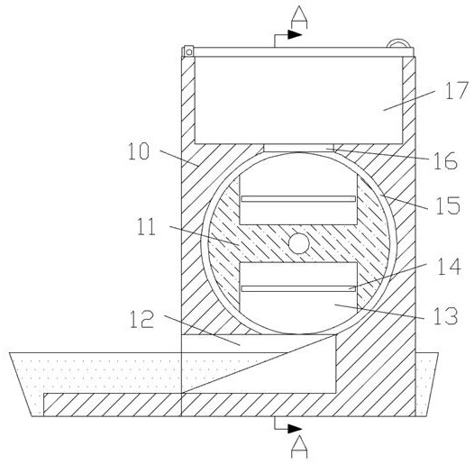
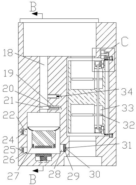
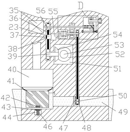
[0021] Such as Figure 1-5As shown, a crayfish feed feeding device that automatically adjusts the feeding amount of the device of the present invention includes a main body box 10, and the main body box 10 is provided with a feed storage chamber 17 with an upward opening. The feed cavity 16 is connected to the side, and the lower side of the feed cavity 16 is connected with a feeding turntable cavity 15. The lower side of the feeding turntable cavity 15 is connected with a feeding cavity 12 with an o...
PUM
 Abstract
Description
Claims
Application Information
 - Generate Ideas
- Intellectual Property
- Life Sciences
- Materials
- Tech Scout
- Unparalleled Data Quality
- Higher Quality Content
- 60% Fewer Hallucinations
Browse by: Latest US Patents, China's latest patents, Technical Efficacy Thesaurus, Application Domain, Technology Topic, Popular Technical Reports.
© 2025 PatSnap. All rights reserved.Legal|Privacy policy|Modern Slavery Act Transparency Statement|Sitemap|About US| Contact US: help@patsnap.com