Supercharge Your Innovation With Domain-Expert AI Agents!

Cabinet leg and adjustment tool

A technology of cabinet legs and tools is applied in the field of tools for adjusting the length of the legs, and can solve the problems of complex tools and the like

Active Publication Date: 2020-10-09
贾斯汀伯纳德穆里根 +1
View PDF5 Cites 0 Cited by
  • Summary
  • Abstract
  • Description
  • Claims
  • Application Information

AI Technical Summary

Problems solved by technology

However, this system uses relatively complex tooling in order to fit and rotate the foot around said foot

Method used


Image

  • Cabinet leg and adjustment tool
  • Cabinet leg and adjustment tool
  • Cabinet leg and adjustment tool

Examples


Embodiment Construction

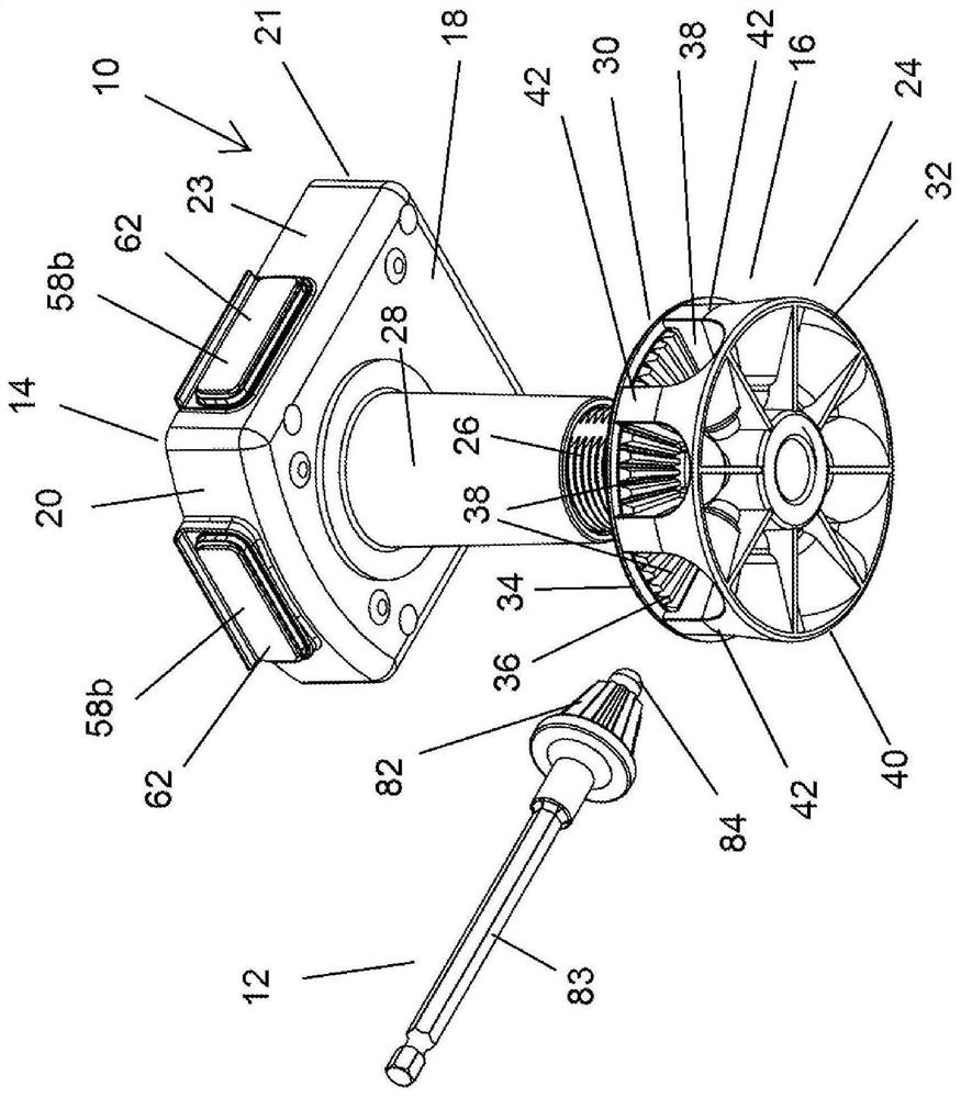
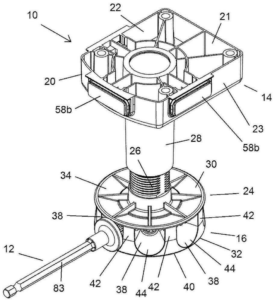
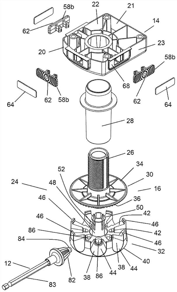
[0053] Referring to these figures, a cabinet leg 10 is shown, which can be fixed under a cabinet, such as a kitchen cabinet, and whose height can be adjusted by means of an adjustment tool 12 .

[0054] The cabinet leg 10 generally includes a body 14 and a foot 16 . The main body 14 is arranged to be secured to the lower surface of the cabinet, and the feet 16 extend downwardly from the main body 14 . The foot 16 is connected to the body 14 such that the foot 16 can be moved toward or away from the body 14 by rotation of a portion of the foot 16 . Rotation of a portion of the foot 16 thus makes it possible to adjust the length of the cabinet leg 10 which can be used to adjust the height and level the cabinet when the cabinet leg 10 is used to support the cabinet.

[0055] In the embodiment shown, the body 14 includes a generally planar lower wall 18 having vertical walls extending upwardly from its periphery. In the illustrated embodiment, the lower wall 18 is rectangular an...


PUM


Abstract

A cabinet leg (10) comprising a body (12) securable to an underside of a cabinet and a shaft (26) engageable with the body (12) such that rotation of the shaft (26) moves the shaft (26) toward or awayfrom the body (12). A foot (16) is secured to a lower end of the shaft (26) comprising a first portion (30) attached to the shaft (26) and a second portion (32) rotatable relative to the first portion (30). A plurality of openings (38) are provided around the periphery of the foot (16) for receiving a first end of a tool (12) such that teeth on the tool (12) engage with teeth (36) on the first portion (30). Rotation of the tool (12) causes rotation of the first portion (30) relative to the second portion (32), thereby rotating the shaft (26) and adjusting the height of the cabinet leg (10).

Description

technical field [0001] The present invention relates to legs for cabinets, such as cupboards, and means for adjusting the length of said legs. Background technique [0002] When installing cabinets such as kitchen cabinets, it is required to level the cabinet after it is in place. In known systems, the legs comprise feet intended to be fitted by bolts. The feet can thus be rotated to shorten or lengthen the legs and thus adjust the height of the cabinet. In such systems, however, it is necessary to reach under the cabinet to grab and rotate the feet for adjustment. This would be difficult, especially when adjusting the rear legs of said cabinet from the front. [0003] Further systems have been proposed in which there is a diversion tool arranged to cooperate with part of said foot. The tool is designed to rotate the legs so that the height of the legs can be adjusted without reaching under the cabinet. However, this system uses relatively complex tools in order to fit ...

Claims


Application Information

Patent Timeline
Patent Type & Authority Applications(China)
IPC IPC(8): A47B91/02
CPCA47B91/024B25B15/004B25B23/0021B25B23/0035B25B17/00B25B21/002A47B91/16F16M7/00F16M11/24
Inventor 贾斯汀·伯纳德·穆里根保罗·西蒙·林格斯爱德华·约瑟夫·库利
Owner 贾斯汀伯纳德穆里根
Features
  • R&D
  • Intellectual Property
  • Life Sciences
  • Materials
  • Tech Scout
  • Unparalleled Data Quality
  • Higher Quality Content
  • 60% Fewer Hallucinations
Learn More