Construction method for underground diaphragm wall under condition of irremovable underground obstacle

A technology for underground diaphragm walls and underground obstacles, which is applied in sheet pile walls, foundation structure engineering, construction, etc., can solve the problems of high pipeline safety risks, difficult soil excavation, and large economic losses, so as to ensure the overall rigidity and The effects of stress safety on the foundation pit and prevention of the risk of falling apart

Pending Publication Date: 2020-10-13
浙江土工岩土科技有限公司
View PDF7 Cites 1 Cited by
  • Summary
  • Abstract
  • Description
  • Claims
  • Application Information

AI Technical Summary

Problems solved by technology

The original construction method of the underground diaphragm wall at the position of the pipeline, when faced with similar obstacles such as the pipe gallery, the following problems occurred: the buried depth of the pipe gallery is relatively deep, and when the groove is formed, it is operated underwater, and it may encounter the pipe gallery and cause internal The risk of pipeline damage; the section size of the pipe gallery is large, and the hydraulic grab is vertically grooved for construction, and the soil directly below is difficult to excavate; the "one groove and two cages" method, there is no steel bar directly below the pipe gallery, and the force on the wall is affected. The rigidity is not enough; the long-term construction and the disturbance of the soil under the pipe gallery cause a great risk to the safety of the pipeline; the economic loss caused by the suspension of the project caused by the influence of the pipeline and the inability to construct is very large

Method used


Image

  • Construction method for underground diaphragm wall under condition of irremovable underground obstacle
  • Construction method for underground diaphragm wall under condition of irremovable underground obstacle

Examples


Embodiment Construction

[0022] The present invention will be described in more detail below in conjunction with the accompanying drawings. It should be noted that the following description of the present invention with reference to the accompanying drawings is only illustrative rather than limiting. Different embodiments can be combined with each other to form other embodiments not shown in the following description.

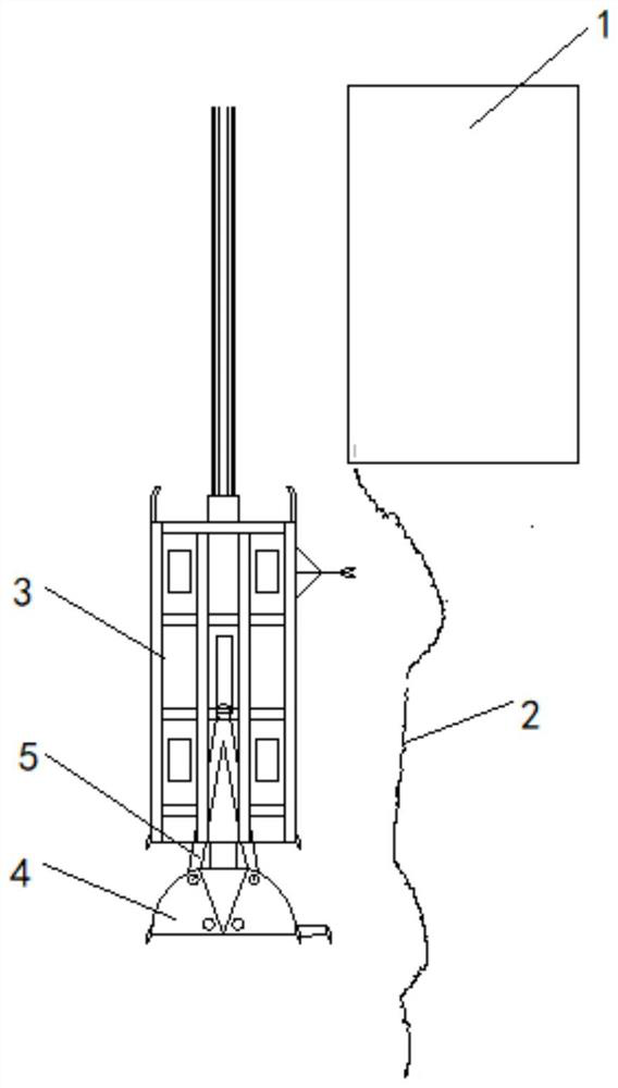
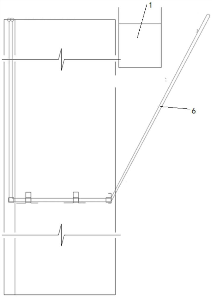
[0023] The invention provides a construction method of an underground diaphragm wall under the condition of an unremovable underground obstacle, which is characterized in that it comprises the following steps:

[0024] Step 1. Make a deep guide wall to the bottom of the pipe gallery 1, and protect the pipe gallery with protective steel plates, specifically: use the method of hanging the well wall upside down to build a deep guide wall to the bottom of the pipe gallery, and use I-shaped steel skeleton and protection The steel plate connects the pipe gallery and the deep guide wall to pr...


PUM


Abstract

The invention relates to a construction method for an underground diaphragm wall under the condition of an irremovable underground obstacle. The construction method comprises the following steps of making a deep guide wall to the bottom of a pipe gallery, and protecting the pipe gallery through protective steel plates; separately forming grooves along the protective steel plates on the both sidesof the pipe gallery through a trenching machine to a set position below the bottom elevation of the pipe gallery; and performing underwater towing and translation on a plurality of reinforcement cagesthrough a crane, so that all the reinforcement cages are horizontally moved to the specified position below the pipe gallery. The pipe gallery is completely wrapped and protected through the protective steel plates, and the situation that a grab bucket collides with the pipe gallery structure by mistake during grooving is avoided; through underwater towing and translation , the breakdown and damage risk caused by uneven stress of the reinforcement cages in the translation process can be avoided, and it is ensured the reinforcement cages are horizontally moved to the specified position below the pipe gallery; and the overall rigidity of a wall and the stress safety of the foundation pit below the pipe gallery are ensured.

Description

technical field [0001] The invention relates to the technical field of underground diaphragm wall construction, in particular to an underground diaphragm wall construction method under the condition of unremovable underground obstacles. Background technique [0002] In recent years, with the rapid development of urban rail transit, the underground diaphragm wall has rapidly become the deep foundation pit of subway stations due to its advantages such as less land occupation, high work efficiency, high rigidity, reliable quality, strong geological adaptability and little impact on the surrounding environment. main form of support. [0003] The construction of the underground diaphragm wall is mainly divided into three parts: trough formation, reinforcement cage installation, and concrete pouring. Under normal circumstances, all underground pipelines and other obstacles in the construction area should be relocated and dealt with before construction, otherwise the trenching con...

Claims


Application Information

Patent Timeline
Patent Type & Authority Applications(China)
IPC IPC(8): E02D5/18
CPCE02D5/18E02D5/187
Inventor 康洪源
Owner 浙江土工岩土科技有限公司
Why Eureka
Try Eureka