Detachable mechanical combination lock

A mechanical combination lock and lock body technology, which is applied in the field of turntable registration type mechanical combination locks, can solve the problems such as the confusion of numbers on the front sight of the knob, the complicated operation process of the registration, and the trouble for users, so as to achieve low cost and strong anti-destructive performance. Turn on the effect of high performance and safety factor

Active Publication Date: 2021-11-23
北京德昱嘉诚科技有限公司
View PDF8 Cites 0 Cited by
  • Summary
  • Abstract
  • Description
  • Claims
  • Application Information

AI Technical Summary

Problems solved by technology

[0005] However, there are certain problems with the "hole-sealed mechanical combination lock", mainly because the registration operation process is relatively complicated: when registering, you need to press each knob first, and insert the convex edge of the knob shaft into the docking groove of the turntable shaft In order to complete the check number operation; after unlocking and locking, in order to prevent the password from being stolen, it is necessary to confuse the numbers corresponding to the sights on each knob plate, that is, the garbled code operation process also needs to be completed by pressing the knob plate first and inserting the convex edge into the docking groove. , causing some trouble to users

Method used


Image

  • Detachable mechanical combination lock
  • Detachable mechanical combination lock
  • Detachable mechanical combination lock

Examples


Embodiment approach 1

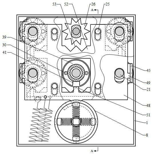
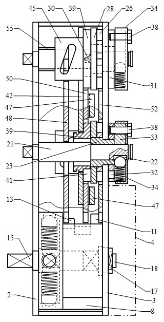
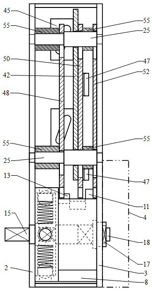
[0067] Such as figure 1 , 2 . As shown in 3, the disengagement type mechanical combination lock includes a lock body 1, a buckle cover 4, a lock outer panel 5 and a handle, and the lock outer panel 5 is equipped with a handle and 6 mutually independent knob plates 6 and corresponding 6 Knob shaft 7. The lock body 1 is in the shape of a rectangle, the side panel located on the outside is the outer side panel 2 of the lock body, the side panel located on the inside is the inner side panel 3 of the lock body, and the inner lower part of the inner side panel 3 of the lock body is assembled with the buckle cover 4, The cavity formed by the two and the outside of the buckle cover 4 are used to assemble the unlocking actuator, and the unlocking and locking are completed by driving the lock bolt and the dead bolt. The lower side of the lock body 1 is provided with a cam mechanism.

[0068] Such as Figures 26 to 33 As shown, the cam mechanism includes a cam 8, a round table 14, a ...

Embodiment approach 2

[0090] Such as Figure 36 As shown, change the code-changing screw hole 37 into a common through hole, that is, the code-changing optical hole 58, change the code-changing bolt 38 into a latch 56, and then assemble a small spring. Wherein, the pin 56 is in the shape of a stepped shaft, and is composed of three sections of shafts with different diameters from the outside to the inside. The shaft at the outer end is used to be inserted into the code-changing hole 32 of the code-changing wheel 31, and the short shaft with a larger diameter in the middle is in the code-changing light. Sliding back and forth in the hole 58, the slender shaft at the inner side end of the latch 56 passes through the corresponding through hole of the wheel cover 34 and stretches out to the outside of the wheel cover 34, and a snap ring groove is provided at the end, and the small spring is sleeved on the latch 56. On the slender shaft, and between the minor axis of latch 56 and the inner side of wheel...

Embodiment approach 3

[0092] Such as Figure 39 , 40 Shown, the co-moving pawl 47 of cross slide plate 42 is canceled. Such as Figure 38 As shown, a circlip groove is provided on the thick shaft of the guide shaft 25, and a circlip is assembled. A backing ring 55 is still assembled between the locking plate 52. When the cross slide 42 slides reciprocatingly along the axial direction of the guide shaft 25, the flashing plate 50 remains motionless, that is, the flashing plate 50 can only move vertically back and forth. The thickness of the follow-up opening 41 in the axial direction of the guide shaft 25 is greater than that of the lug 51. When the knob shaft 7 turns to the correct password position and the cross slide 42 moves outward, the lug 51 can still be inserted into the follow-up opening 41. Such as Figure 37 As shown, in this solution, the thickness of the follower wheel 39 needs to be appropriately increased. No matter how the follower wheel 39 slides, the inner side end surface of th...


PUM


Abstract

A detachable mechanical combination lock, which relates to the field of turntable-type mechanical combination locks, in which the operation of checking numbers is completed by directly rotating six knobs; the cam mechanism is driven by the handle to rotate to realize unlocking and locking; After the linkage shaft movably connected with the shaft passes through the lock body, it first drives the overload protection device and the code changing device to rotate, and then returns to the lock body along the coaxial axis, and drives the saw gear and the thumb wheel to rotate, and finally makes the 6 follower wheels with gaps Follow the rotation. When unlocking, the cam first pushes the locking plate to insert into the tooth groove of the saw gear, and the knob plate can no longer rotate, and then the push-pull plate pushes the oblique long hole on the horizontal slide plate to make the follower wheel move laterally and separate from the thimble on the dial wheel Contact, finally make the flashboard insert in the gap of each follower wheel, the cam continues to rotate and unlock, so it is impossible to technically open the lockset. When the handle or the knob is twisted forcefully, both can rotate idly; password change operation and garbled code operation are simple and easy.

Description

technical field [0001] The invention relates to the field of turntable-marked mechanical coded locks, in particular to a detachable mechanical coded lock. Background technique [0002] The turntable matching mechanical code lock has a wide range of applications. As a mechanical blocking mechanism, it is often used on file cabinets, vaults, safes, safes, and security doors. However, there have been a series of problems for a long time. First, the registration process takes too long 1. The operation is inconvenient; second, the password cannot be changed, which is very inconvenient for hiding and storing the password or remembering the password; third, the anti-theft opening performance cannot be opened technically, because the knob plate is in direct contact with the blocking mechanism inside the lock through the knob shaft. It is easy to crack by hearing, feeling and experience; fourth, the anti-destructive performance is not good enough, especially the combination lock inst...

Claims


Application Information

Patent Timeline
Patent Type & Authority Patents(China)
IPC IPC(8): E05B37/12E05B15/00E05B17/20
CPCE05B15/00E05B15/004E05B17/2084E05B37/0048E05B37/12
Inventor 韩现龙吕雪寒齐伟
Owner 北京德昱嘉诚科技有限公司
Why Eureka
Try Eureka