Magnetic drive type mechanical coded lock

A mechanical combination lock and magnetic drive technology, applied in the field of magnetic drive mechanical combination locks, can solve the problems such as the confusion of the numbers of the dial front sight, the complicated operation process of the sign, the trouble for the user, etc., to achieve a simplified structure, easy memory, and convenient locks. Assembly effect

Active Publication Date: 2020-10-02
烟台三环锁业集团浦江有限公司
View PDF8 Cites 0 Cited by
  • Summary
  • Abstract
  • Description
  • Claims
  • Application Information

AI Technical Summary

Problems solved by technology

[0005] However, there are certain problems with the "hole-sealed mechanical combination lock", mainly because the registration operation process is relatively complicated: when registering, you need to press each knob first, and insert the convex edge of the knob shaft into the docking groove of the turntable shaft In order to complete the check number operation; after unlocking and locking, in order to prevent the password from being stolen, it is necessary to confuse the numbers corresponding to the sights on each knob plate, that is, the garbled code operation process also needs to be completed by pressing the knob plate first and inserting the convex edge into the docking groove. , causing some trouble to users

Method used


Image

  • Magnetic drive type mechanical coded lock
  • Magnetic drive type mechanical coded lock
  • Magnetic drive type mechanical coded lock

Examples


Embodiment approach 1

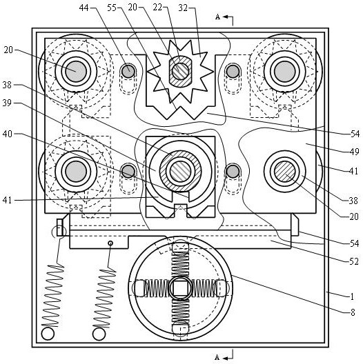
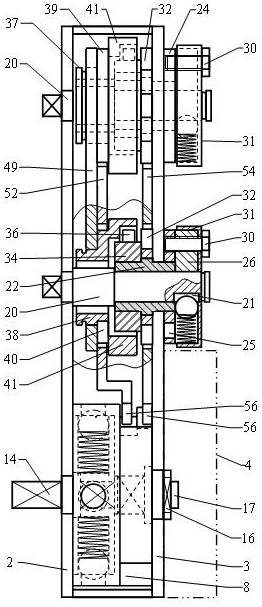
[0069] Such as figure 1 , 2 , 3, the magnetically driven mechanical combination lock includes a lock body 1, a buckle cover 4, a lock outer panel 5 and a handle, and the lock outer panel 5 is equipped with a handle and 6 mutually independent knob plates 6 and corresponding 6 A knob shaft 7. The lock body 1 is in the shape of a rectangle, the side panel located on the outside is the outer side panel 2 of the lock body, the side panel located on the inside is the inner side panel 3 of the lock body, and the inner lower part of the inner side panel 3 of the lock body is assembled with the buckle cover 4, The cavity formed by the two and the outside of the buckle cover 4 are used to assemble the unlocking actuator, and the unlocking and locking are completed by driving the lock bolt and the dead bolt. The lower side of the lock body 1 is provided with a cam mechanism.

[0070] Such as Figures 25 to 32 As shown, the cam mechanism includes a cam 8, a round table 13, a round tab...

Embodiment approach 2

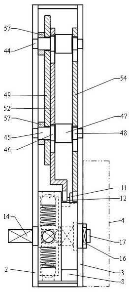
[0090] Such as Figure 35 , 36 , 38, the plate 52 of the lockset of the present invention can also be replaced by a flat plate without bending. Such as Figure 37 As shown, the plate shaft 46 of the corresponding guide shaft 44 moves between the limit shaft 47 and the lock plate shaft 48 and has the same diameter as the lock plate shaft 48 . A backing ring 57 is movably assembled between the no-bend insert plate and the locking plate. Such as Figure 39 , 40 , Shown in 41, the step in the middle part of the follower wheel 37 is the notch wheel and has been canceled, and the follower notch 40 is arranged on the outer circular surface of the annular wheel 41 of the follower wheel 37, and the lock performance remains unchanged.


PUM


Abstract

The invention discloses a magnetic drive type mechanical coded lock, and relates to the field of rotary disc number matching type mechanical coded locks. Number matching operation is completed by directly rotating six knob discs, lever handles drive a cam mechanism to rotate to realize unlocking and locking; during number matching, after the linkage shafts movably connected with the rotary knob shafts penetrate through a lock body, an overload protection device and a code changing device are driven to rotate firstly, then the linkage shafts coaxially return into the lock body and drive sawtooth wheels and a magnetic driving wheel to rotate synchronously, and follower wheels with notches rotate along with the linkage shafts. Due to the fact that the magnetic driving wheel does not make contact with the follower wheels and is driven only by the attraction force of a strong magnet, a cam pushes a locking plate to be inserted into the tooth grooves of the sawtooth wheels firstly in the unlocking process, the knob discs cannot rotate any more, then an inserting plate is inserted into the notches of the follower wheels, the cam continues to rotate to unlock the lock, and therefore the lock cannot be technically unlocked; when the lever handles or the knob discs are strongly twisted, the lever handles and the knob discs can idle; password changing and messy code operation are simple and easy to implement, and the magnetic drive type mechanical coded lock is particularly suitable for important occasions with low use frequency.

Description

technical field [0001] The invention relates to the field of turntable-marked mechanical coded locks, in particular to a magnetically driven mechanical coded lock. Background technique [0002] The turntable matching mechanical code lock has a wide range of applications. As a mechanical blocking mechanism, it is often used on file cabinets, vaults, safes, safes, and security doors. However, there have been a series of problems for a long time. First, the registration process takes too long 1. The operation is inconvenient; second, the password cannot be changed, which is very inconvenient for hiding and storing the password or remembering the password; third, the anti-theft opening performance cannot be opened technically, because the knob plate is in direct contact with the blocking mechanism inside the lock through the knob shaft. It is easy to crack by hearing, feeling and experience; fourth, the anti-destructive performance is not good enough, especially the combination ...

Claims


Application Information

Patent Timeline
Patent Type & Authority Applications(China)
IPC IPC(8): E05B37/12E05B47/00E05B15/00
CPCE05B37/12E05B37/0048E05B47/0038E05B15/00
Inventor 吕雪寒齐伟
Owner 烟台三环锁业集团浦江有限公司
Why Eureka
Try Eureka