
Fire-fighting smoke exhaust valve

A valve and fire-fighting technology, which is applied in the direction of lifting valves, valve details, valve devices, etc., can solve the problems of affecting smoke discharge, lower survival probability, and low safety factor, so as to increase the possibility of escape, efficient smoke discharge, and increase safety Effect

Inactive Publication Date: 2020-10-13
姜平乐
View PDF0 Cites 0 Cited by
  • Summary
  • Abstract
  • Description
  • Claims
  • Application Information

AI Technical Summary

Problems solved by technology

[0002] In the prior art, most of the fire-fighting smoke exhaust valves are used in conjunction with ventilation shafts. Conventional smoke exhaust valves cannot effectively isolate the smoke at the ventilation shafts, so that the smoke is at the top side and the personnel can effectively pass through the ventilation. Well, due to the existence of the ventilation shaft and the smoke exhaust valve, in a fire, the smoke will directly enter the ventilation shaft through the smoke exhaust valve, causing more smoke to accumulate in the ventilation shaft, and because the control structure of the ventilation valve in the conventional design is too simple , so that the discharge process of air and smoke is relatively slow, which affects the discharge of smoke and fills the room and passages with smoke, making it difficult for people to breathe or reduce the probability of survival when escaping, which makes the equipment unable to perform normally to meet the needs of people. Daily needs, and the corresponding safety factor is also low

Method used


Image

  • Fire-fighting smoke exhaust valve
  • Fire-fighting smoke exhaust valve
  • Fire-fighting smoke exhaust valve

Examples


Embodiment Construction

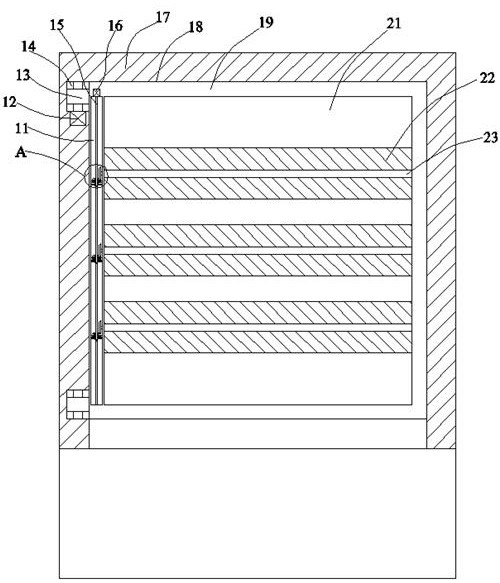
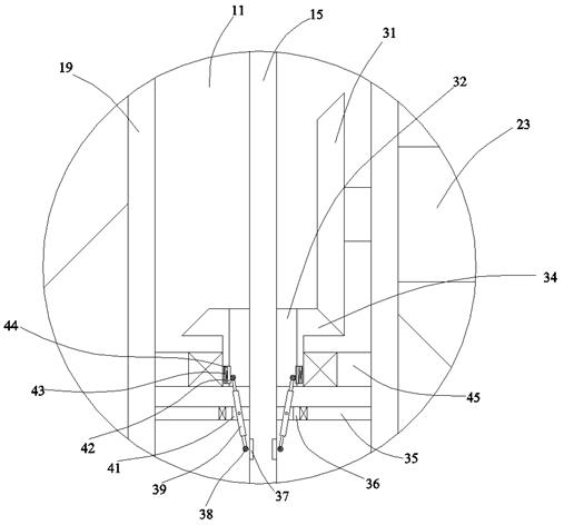
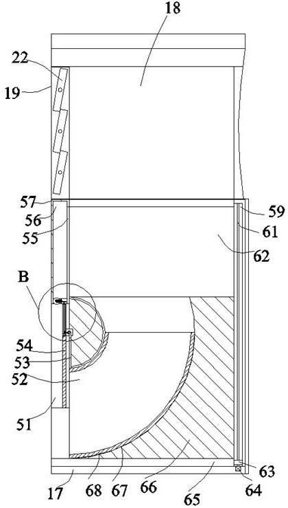
[0022] Such as Figure 1-Figure 4 As shown, the present invention is described in detail. For the convenience of description, the orientations mentioned below are now stipulated as follows: figure 1 The up, down, left, right, front and back directions of the projection relationship itself are consistent. A fire-fighting and smoke exhaust valve of the present invention includes a box body 17, a channel cavity 18 is arranged in the box body 17, and a frame 19 is arranged on one side of the channel cavity 18. Between the frame 19 and the box body 17, a rotating blocking device is provided to rotate the frame 19 and change the channel space inside the frame 19 to effectively block smoke, etc., and the lower side of the rotating blocking device is provided with Located in the channel cavity 18 and utilizes the lifting method and the ring structure to communicate with the lower side of the channel cavity 18 and the external space so that the lifting ring in the channel cavity 18 can...


PUM


Abstract

The invention discloses a fire-fighting smoke exhaust valve. The fire-fighting smoke exhaust valve comprises a box body, wherein a channel cavity is arranged in the box body, a frame is arranged at one side of the channel cavity, and a rotating blocking device for rotating the frame and changing a channel space in the frame so as to block smoke effectively is arranged between the frame and the boxbody; the lower side of the rotating blocking device is provided with a lifting annular pipe device located in the channel cavity and using a lifting method and an annular structure, so that the channel cavity communicates with the position of the lower side of an external space in the channel cavity and smoke damage can be avoided when personnel pass through the channel cavity; the equipment adopts the control of internal blades of a fire valve, so that the equipment can turnover some blades according to actual situations, the smoke discharge is more efficient; and moreover, a structure forthe personnel to enter a pipeline to escape is formed so as to isolate the smoke, and the possibility and safety of escaping when the personnel enter the pipeline are increased.

Description

technical field [0001] The invention relates to the technical field of fire-fighting equipment, in particular to a fire-fighting and smoke exhaust valve. Background technique [0002] In the prior art, most of the fire-fighting smoke exhaust valves are used in conjunction with ventilation shafts. Conventional smoke exhaust valves cannot effectively isolate the smoke at the ventilation shafts, so that the smoke is at the top side and the personnel can effectively pass through the ventilation. Well, due to the existence of the ventilation shaft and the smoke exhaust valve, in a fire, the smoke will directly enter the ventilation shaft through the smoke exhaust valve, causing more smoke to accumulate in the ventilation shaft, and because the control structure of the ventilation valve in the conventional design is too simple , so that the discharge process of air and smoke is relatively slow, which affects the discharge of smoke and fills the room and passages with smoke, making...

Claims


Application Information

Patent Timeline
Patent Type & Authority Applications(China)
IPC IPC(8): F16K1/22F16K31/04F16K31/53A62C35/68
CPCA62C35/68F16K1/221F16K1/223F16K31/04F16K31/53
Inventor 姜平乐
Owner 姜平乐
Learn More