
Control system of automatic electromechanical equipment

A technology for control systems and electromechanical equipment, applied in general control systems, control/regulation systems, computer control, etc., can solve problems such as poor applicability, different input currents, and cumbersome operations, so as to improve installation efficiency and improve application versatility. , to improve the effect of use

Pending Publication Date: 2020-10-13
熊鹰
View PDF9 Cites 0 Cited by
  • Summary
  • Abstract
  • Description
  • Claims
  • Application Information

AI Technical Summary

Problems solved by technology

[0002] The control system of electromechanical equipment is mainly used to control the power supply status of each electromechanical equipment, so as to realize the cooperative work of multiple electromechanical equipment, but because the input voltage and input current of each electromechanical equipment are different, the electromechanical equipment in the prior art The equipment control system needs to set up an independent voltage and current conversion device for the input voltage and input current of each electromechanical equipment. Its operation is cumbersome and its applicability is poor, which cannot meet the needs of diversified electromechanical equipment in the prior art.

Method used


Image

  • Control system of automatic electromechanical equipment

Examples


Embodiment Construction

[0016] The following will clearly and completely describe the technical solutions in the embodiments of the present invention with reference to the accompanying drawings in the embodiments of the present invention. Obviously, the described embodiments are only some, not all, embodiments of the present invention. Based on the embodiments of the present invention, all other embodiments obtained by persons of ordinary skill in the art without creative work, any modifications, equivalent replacements, improvements, etc., shall be included in the protection scope of the present invention Inside.

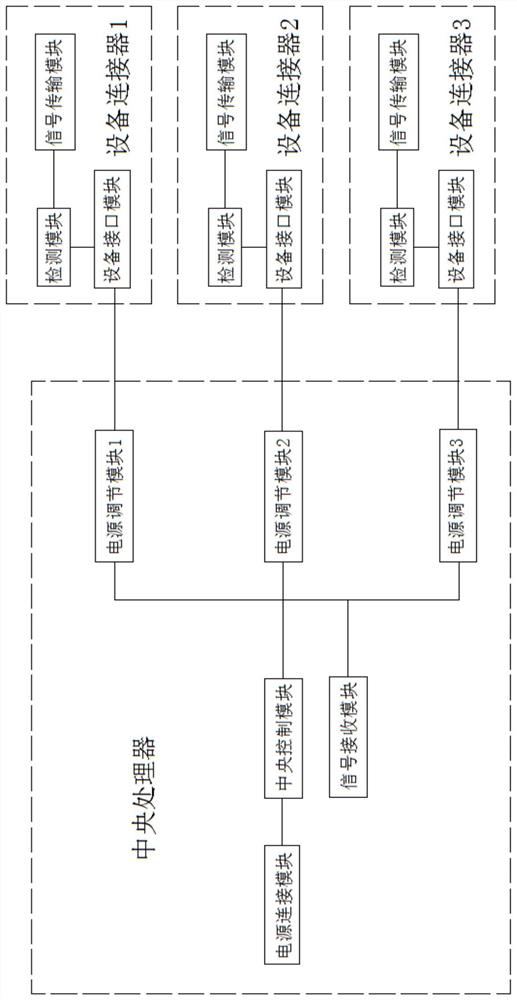
[0017] Such as figure 1 As shown, the control system of the automated electromechanical equipment in this embodiment includes a central processing unit and a device connector, and there are several device connectors that are all connected to the central processor line;

[0018] The device connector includes a device interface module for connecting with the device and supplying power to t...


PUM


Abstract

The invention discloses a control system of automatic electromechanical equipment. The system comprises a central processing unit, and a plurality of equipment connectors which are in line connectionwith the central processing unit. Each equipment connector comprises an equipment interface module, a detection module and a signal transmission module; the signal input end of each detection module is in line connection with the signal output end of the corresponding equipment interface module, the signal output end of each detection module is in line connection with the signal input end of the corresponding signal transmission module, and the signal output end of each signal transmission module is connected with the central processing unit; the central processing unit comprises a central control module, a power supply adjusting module and a signal receiving module; and the signal input end of each signal receiving module is connected with the signal output end of the corresponding signaltransmission module, the signal output ends of the signal receiving module and the central control module are in line connection with the signal input end of the power supply adjusting module, and the signal output end of the power supply adjusting module is in line connection with the signal input end of the equipment interface module.

Description

technical field [0001] The invention relates to the field of electromechanical automation, in particular to a control system for automatic electromechanical equipment. Background technique [0002] The control system of electromechanical equipment is mainly used to control the power supply status of each electromechanical equipment, so as to realize the cooperative work of multiple electromechanical equipment, but because the input voltage and input current of each electromechanical equipment are different, the electromechanical equipment in the prior art The equipment control system needs to set up an independent voltage and current conversion device for the input voltage and input current of each electromechanical equipment. The operation is cumbersome and the applicability is poor, which cannot meet the needs of diversified electromechanical equipment in the prior art. Contents of the invention [0003] The purpose of the present invention is to solve the above problems...

Claims


Application Information

Patent Timeline
Patent Type & Authority Applications(China)
IPC IPC(8): G05B19/042G01R19/00
CPCG05B19/0423G01R19/00G05B2219/25257
Inventor 熊鹰
Owner 熊鹰
Learn More