Valve flow coefficient convenient calculation method based on CFD simulation

A calculation method and simulation calculation technology, applied in the direction of calculation, computer-aided design, design optimization/simulation, etc., can solve the problems of high valve flow coefficient cost, valve size specification limit, large calculation result error, etc., to shorten the research and development cycle, The effect of avoiding waste and saving costs

Pending Publication Date: 2020-10-13
JIANGSU SHENTONG VALVE +1
View PDF1 Cites 9 Cited by
  • Summary
  • Abstract
  • Description
  • Claims
  • Application Information

AI Technical Summary

Problems solved by technology

[0009] The purpose of the present invention is to overcome the high cost of using the experimental method to calculate the valve flow coefficient, the limitation on the size of the valve, and the existing CFD simulation method is mainly established by experience, which is limited by the professional level of the operator. The model is too long and the calculation period is long. The model is too short, the calculation results have large errors, and the need for multiple modeling calculations requires a large amount of calculations. A convenient calculation method for valve flow coefficient based on CFD simulation is proposed.

Method used


Image

  • Valve flow coefficient convenient calculation method based on CFD simulation
  • Valve flow coefficient convenient calculation method based on CFD simulation
  • Valve flow coefficient convenient calculation method based on CFD simulation

Examples


Embodiment Construction

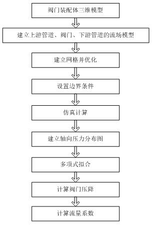
[0037] The operation process of this embodiment is as follows:

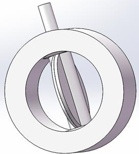
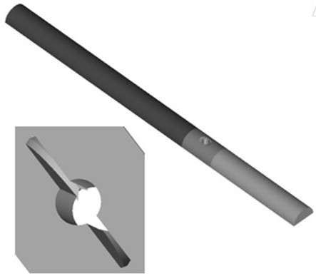
[0038] (1) Based on the 3D model of the valve assembly, extract the flow field models of the upstream pipeline, the valve, and the downstream pipeline; taking the DN500 central butterfly valve as an example, use Solidworks to establish the assembly model such as figure 2 , after simplifying the small structures such as rounding, chamfering and threaded holes in this model, the inlet and outlet are respectively connected with an upstream pipeline with a length of 21 times the nominal diameter and a downstream pipeline with a length of 10 times the nominal diameter; then extract the upstream pipeline, valve, The "valve-pipe" flow field model of the combination of downstream pipelines, such as image 3 , to symmetrically divide the flow field model to save computing resources;

[0039] (2) Mesh the flow field model, consider the flow boundary conditions required by the working conditions, and combine multiple mesh...


PUM


Abstract

The invention discloses a valve flow coefficient convenient calculation method. Specifically, the valve flow coefficient is simply and conveniently calculated by combining a CFD simulation method witha linear fitting method. The method mainly comprises the following steps: establishing flow field models of an upstream pipeline, a valve and a downstream pipeline based on a valve assembly three-dimensional model; dividing the flow field model into grids and optimizing the model grids; applying a re-optimized grid to set a boundary condition to perform simulation calculation; intercepting a plurality of cross sections of the upstream pipeline to acquire an average pressure value; determining a linear fitting order according to the axial pressure distribution diagram, and performing linear fitting; combining the total pressure difference of the pipeline with the valve obtained in the simulation calculation result; and calculating a valve flow coefficient by using the valve pressure difference. Compared with an existing CFD simulation method, the valve flow coefficient can be calculated only through one-time modeling, the calculation steps can be greatly simplified, the calculation amount can be reduced, the flow coefficients of various types of valves can be accurately predicted, and wide application prospects are achieved.

Description

[0001] Technical field [0002] The invention belongs to the field of valve flow capacity calculation, and in particular relates to a convenient method for calculating valve flow coefficient by using a CFD simulation method combined with a linear fitting method. Background technique [0003] Flow coefficient is an important performance index related to valve energy efficiency, and an effective method to evaluate valve flow coefficient is extremely important for the valve industry. Currently, the evaluation of the valve flow coefficient is usually performed by theoretical estimation or experimental measurement. Theoretical estimates do not reflect the effects of detailed valve structures and thus often result in reduced computational accuracy. The time and equipment costs required for experimental measurements are too high. Especially for some valves, which involve special dimensions or structures, it is difficult to measure their flow coefficients experimentally. In additio...

Claims


Application Information

Patent Timeline
Patent Type & Authority Applications(China)
IPC IPC(8): G06F30/23G06F113/08G06F113/14G06F119/14
CPCG06F30/23G06F2113/08G06F2113/14G06F2119/14
Inventor 周晓明刘浩陈林
Owner JIANGSU SHENTONG VALVE
Why Eureka
Try Eureka