CFD simulation and grid self-adaption based valve flow coefficient calculating method

A valve flow and coefficient calculation technology, applied in the direction of calculation, electrical digital data processing, special data processing applications, etc., can solve the problems of high valve flow coefficient cost, valve size specification restrictions, and limited calculation accuracy, so as to improve the boundary layer Grid, reduce workload and difficulty, improve the effect of simulation accuracy

Active Publication Date: 2016-06-15
JIANGSU SHENTONG VALVE +1
View PDF5 Cites 27 Cited by
  • Summary
  • Abstract
  • Description
  • Claims
  • Application Information

AI Technical Summary

Problems solved by technology

[0007] The purpose of the present invention is to overcome the problems of high cost and long period for calculating the valve flow coefficient by using the experimental method, limitations on the size and specification of the valve, artificially encrypted grids in the existing CFD simulation method, and calculation accuracy limited by the professional level of the operator. A Calculation Method of Valve Discharge Coefficient Based on CFD Simulation and Grid Adaptation

Method used


Image

  • CFD simulation and grid self-adaption based valve flow coefficient calculating method
  • CFD simulation and grid self-adaption based valve flow coefficient calculating method
  • CFD simulation and grid self-adaption based valve flow coefficient calculating method

Examples


Embodiment 1

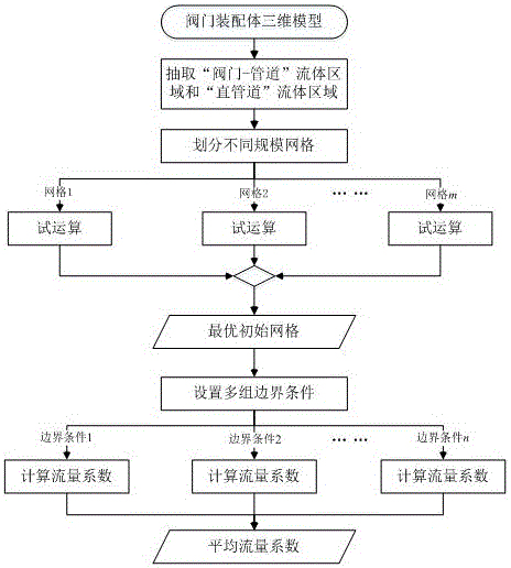
[0037] The operation steps of this embodiment are as follows:

[0038] (1) Establish flow field model and mesh division

[0039] Taking the DN500 eccentric butterfly valve as an example, use Solidworks to build an assembly model. After simplifying the small structures such as rounding, chamfering and threaded holes in this model, connect pipes with a length of 5 times the nominal diameter and 10 times the nominal diameter at the inlet and outlet. ; Then extract the "valve-pipe" flow field model with a total length of 7857 mm, and establish a "straight pipe" flow field model with a length 15 times the nominal diameter, with a total length of 7500 mm.

[0040] Using ANSYSICEMCFD pre-processing software, the "valve-pipe" flow field model is divided into mixed meshes, and the "straight pipe" flow field model is all divided into structural meshes.

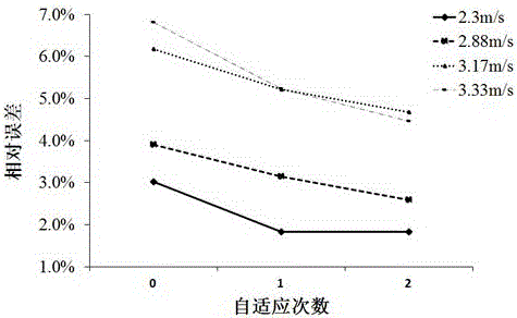
[0041] (2) Judging the optimal initial grid

[0042] For the "valve-pipeline" flow field model, an inlet flow rate of 2.3m / s is set,...

Embodiment 2

[0063] The operation process of this embodiment is as follows:

[0064] (1) Establish flow field model and mesh division

[0065] Taking the DN100 midline butterfly valve as an example, use Solidworks to build an assembly model. After simplifying the small structures such as rounding, chamfering and threaded holes in this model, connect pipes with 5 times the nominal diameter and 10 times the nominal diameter at the inlet and outlet respectively. ; Then extract the "valve-pipe" flow field model, and establish a "straight pipe" flow field model with a length 15 times the nominal diameter.

[0066] Using ANSYSICEMCFD pre-processing software, the "valve-pipe" flow field model is divided into mixed meshes, and the "straight pipe" flow field model is all divided into structural meshes.

[0067] (2) Determine the optimal initial grid

[0068] For the "valve-pipe" flow field model, this study carried out simulation calculations at an inlet flow rate of 31.8kg / s, with four initial g...


PUM


Abstract

The invention discloses a CFD simulation and grid self-adaption based valve flow coefficient calculating method. The CFD simulation and grid self-adaption based valve flow coefficient calculating method comprises the main steps that a 'valve-pipe' flow field model and a 'straight pipeline' flow field model are extracted based on a valve assembly body three-dimensional model; initial grids are divided for the flow field models, wherein multiple groups of initial grids different in scale are divided for the 'valve-pipe' flow field model; trial operation is performed by applying the groups of initial grids respectively, the change tends with grid scales of the obtained pressure differences are compared to select optimal initial grids; the optimal initial grids are applied to set different boundary conditions, and simulating calculation of corresponding flow coefficients is performed by combining a grid self-adaption technology; finally, the arithmetic average of the obtained flow coefficients is obtained to serve as a valve flow coefficient prediction result. The CFD simulation and grid self-adaption based valve flow coefficient calculating method can more rapidly and flexibly predict the flow capacity of a valve under various conditions, shorten a development period and improve the design quality and can effectively improve the calculation accuracy and reduce the dependence on specialization level of operators.

Description

Technical field [0001] The invention relates to the field of calculating the flow capacity of a valve, and is embodied in the calculation of the flow coefficient of the valve by a method combining CFD and grid self-adaptation. Background technique [0002] The flow coefficient of the valve refers to the total flow of the medium in the pipeline flowing through the valve under constant pressure conditions per unit time. The flow coefficient reflects the flow capacity and energy-saving and environmental protection performance of the valve, and is an important process parameter and technical index of the valve. At present, many domestic valve manufacturers use the flow coefficient measured by the experimental method as the standard to measure the flow capacity of the valve, but the cost of the experiment is high, the cycle is long, and it consumes a lot of manpower and material resources. [0003] With the development of computer technology and computational fluid dynamics (Com...

Claims


Application Information

Patent Timeline
Patent Type & Authority Applications(China)
IPC IPC(8): G06F17/50
CPCG06F30/367
Inventor 周晓明汪志琨张逸芳
Owner JIANGSU SHENTONG VALVE
Why Eureka
Try Eureka