Combined hole sublevel open-stope subsequent filling mining method

A backfill mining method and combined hole technology, which is applied in the fields of backfill, ground mining, mining equipment, etc., can solve the problems of large mining dilution loss, large influence range, damage to the surrounding rock of the upper and lower walls, etc., so as to reduce the amount of mining and cutting works. , The effect of reducing the amount of mining quasi engineering, low loss and high efficiency recovery

Inactive Publication Date: 2020-10-16
CHINA MINMETALS CHANGSHA MINING RES INST
View PDF14 Cites 0 Cited by
  • Summary
  • Abstract
  • Description
  • Claims
  • Application Information

AI Technical Summary

Problems solved by technology

However, when the dip angle of the ore body changes greatly, especially the sharp pinch-out thickness of the upper part of the ore body decreases sharply, and the conventional segmented medium-deep hole and subsequent filling mining method is adopted, due to the large impact range of the medium-deep hole blasting, the upper and lower The surrounding rocks are destroyed together with the ore body. Therefore, the loss of mining dilution will be huge, resulting in uncontrollable ore grades, and even waste rocks, which will seriously affect the mining loss indicators and mineral processing recovery rate of mining enterprises.
[0004] In order to solve the problems of difficulty in controlling the dilution loss and uncontrollable ore grade when adopting the mining method of sectioned middle and deep holes followed by filling in the mining of ore bodies with large changes in occurrence and inclination angles, the invention provides a combination hole Segmented empty stop and then fill mining method

Method used


Image

  • Combined hole sublevel open-stope subsequent filling mining method
  • Combined hole sublevel open-stope subsequent filling mining method
  • Combined hole sublevel open-stope subsequent filling mining method

Examples


Embodiment Construction

[0024] The technical solutions of the various embodiments of the present invention will be clearly and completely described below in conjunction with the accompanying drawings. Obviously, the described embodiments are only part of the embodiments of the present invention, not all of them; based on the embodiments of the present invention, All other embodiments obtained by persons of ordinary skill in the art without creative efforts fall within the protection scope of the present invention.

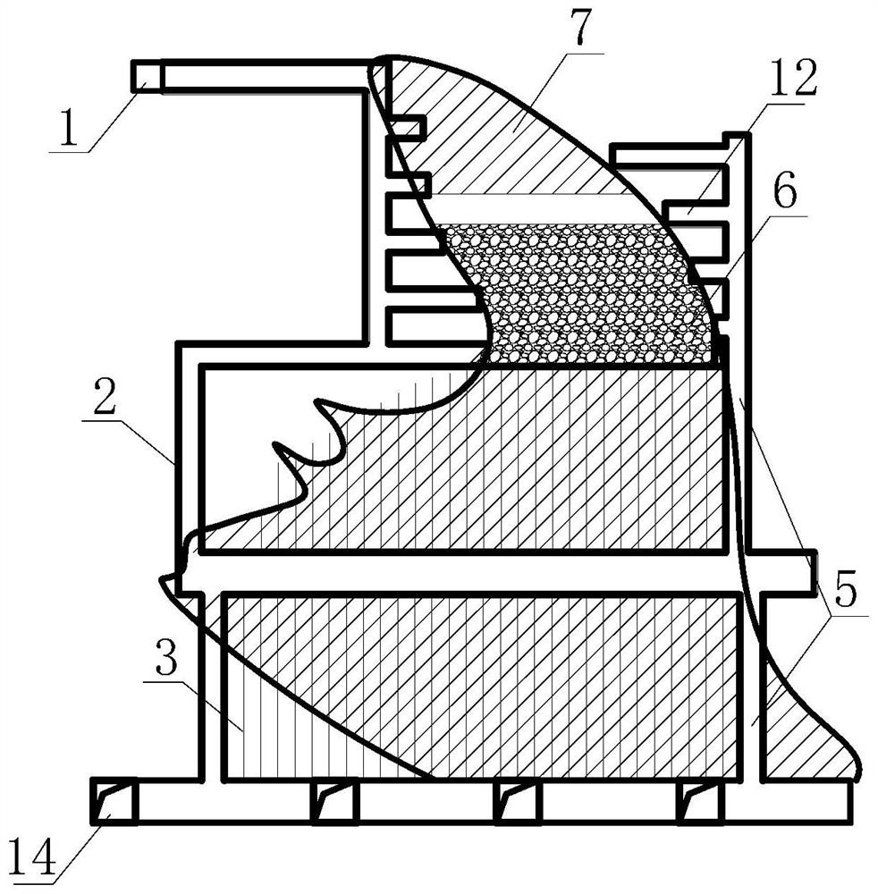
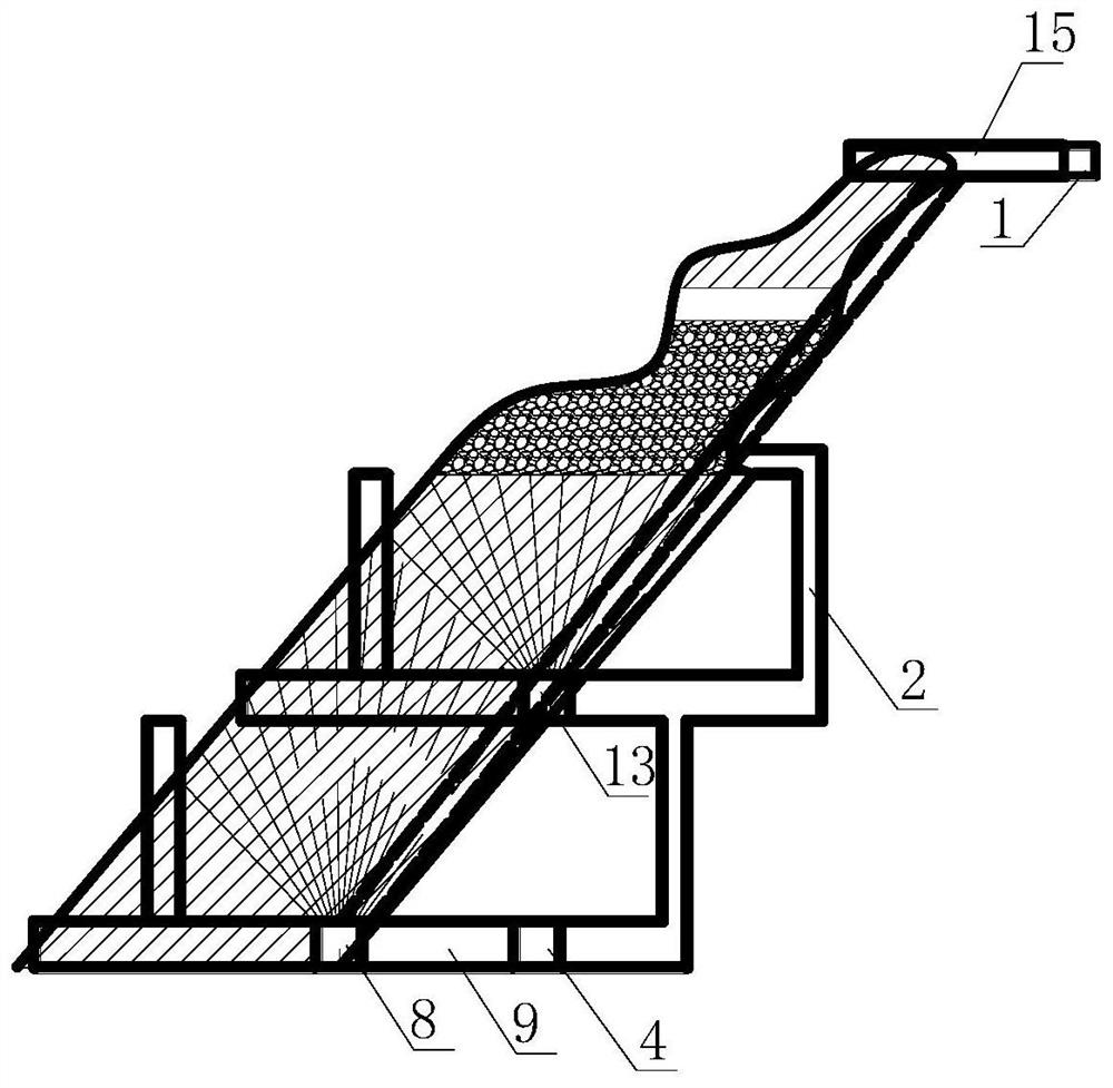
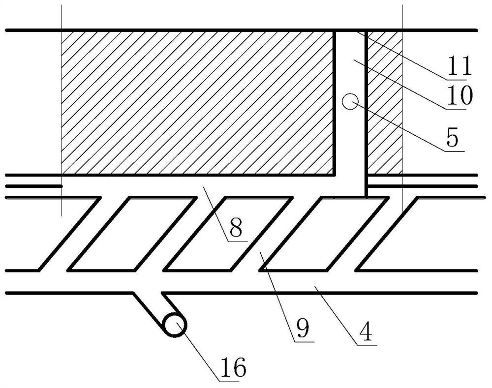
[0025] Such as figure 1 , figure 2 , image 3 As shown, the present invention provides a kind of combination hole subsection empty field subsequent filling mining method, which comprises the following steps:

[0026] 1) The stope is arranged along the direction of the ore body. The length is 40-50m, the width is the thickness of the ore body, and the height is the height of the middle section. According to the occurrence of the ore body, the stope is divided into the upper shallow hol...


PUM


Abstract

The invention discloses a combined hole sublevel open-stope subsequent filling mining method, which is especially suitable for ore body stoping with medium ore rock stability, medium average thicknessor above, large attitude change and sharply-thinned upper thickness. A stope is arranged along an ore body movement direction, the width of the stope is ore body thickness, the height of the stope ismiddle-section height, and the stope is divided into an upper shallow hole shrinkage stoping area and a lower sublevel open-stope stoping area according to an ore body attitude; firstly, the upper shallow hole shrinkage stoping area is subjected to stoping, and then, the lower sublevel open-stope stoping area is subjected to stoping; the upper shallow hole shrinkage stoping area is subjected to stoping by a shallow hole, the lower sublevel open-stope stoping area is subjected to stoping by a mid-depth hole, most ores which collapse from the upper shallow hole shrinkage stoping area and ores which collapse from the lower sublevel open-stope stoping area are shoveled from a bottom ore discharging structure together; and after stope stoping and ore removal are finished, each channel of the stope is plugged, and then, a goaf is filled. The combined hole sublevel open-stope subsequent filling mining method has the advantages of a low depletion loss rate, a small stope preparation cutting engineering quantity and the like.

Description

technical field [0001] The invention belongs to the field of underground mining, and in particular relates to a mining method for combined hole segmentation and subsequent filling, which is especially suitable for mining of ore bodies with moderately stable ore rocks, average thickness above medium thickness, large occurrence changes, and sharply thinning upper thickness. Background technique [0002] When mining moderately stable orebodies above medium thickness, the segmented medium-deep hole and subsequent filling mining method is generally adopted. Then use the YGZ-90 drilling rig or rock drilling jumbo to construct upward fan-shaped medium-deep holes in the segmented rock drilling roadway, and use the cutting groove as the free surface to retreat the ore collapse, and all the ore collapsed by the ore body into the bottom mining structure, and then use a scraper to extract ore from the bottom structure. At the same time, in order to ensure the strength and efficiency of...

Claims


Application Information

Patent Timeline
Patent Type & Authority Applications(China)
IPC IPC(8): E21C41/22E21F1/00E21F15/00F42D3/04F42D1/00
CPCE21C41/22E21F1/006E21F15/005F42D1/00F42D3/04
Inventor 李强刘东锐李向东盛佳李永辉周益龙
Owner CHINA MINMETALS CHANGSHA MINING RES INST
Why Eureka
Try Eureka