Differential pressure flow testing device for electromagnetic valve of automobile composite braking system

A flow test device and composite braking technology, applied in the direction of detecting fluid flow by measuring differential pressure, volume/mass flow generated by mechanical effects, etc. The pressure difference relationship curve and other problems can achieve the effect of simple test principle, correct selection of filter mesh, and convenient test.

Pending Publication Date: 2020-10-16
NINGBO TUOPU GROUP CO LTD
View PDF0 Cites 1 Cited by
  • Summary
  • Abstract
  • Description
  • Claims
  • Application Information

AI Technical Summary

Problems solved by technology

[0003] The flow characteristics of the solenoid valve mainly depend on the structural characteristics of the solenoid valve itself and the pressure difference environment in which it is located. If the flow rate of the solenoid valve is too small, it may cause its braking response time to be too slow, which does not meet the requirements of fast response of braking products.
Therefore, the solenoid valve in the automobile brake actuator needs to be tested to obtain the relationship curve between flow and pressure difference to determine whether it meets the design requirements. The current solenoid valve test device has a complicated structure and cannot quickly obtain the relationship between flow and pressure difference. And it is impossible to test the influence of the filter on the solenoid valve on the pressure difference

Method used


Image

  • Differential pressure flow testing device for electromagnetic valve of automobile composite braking system
  • Differential pressure flow testing device for electromagnetic valve of automobile composite braking system
  • Differential pressure flow testing device for electromagnetic valve of automobile composite braking system

Examples


Embodiment Construction

[0016] The following will clearly and completely describe the technical solutions in the embodiments of the present invention with reference to the accompanying drawings in the embodiments of the present invention. Obviously, the described embodiments are only some, not all, embodiments of the present invention. Based on the embodiments of the present invention, all other embodiments obtained by persons of ordinary skill in the art without making creative efforts belong to the protection scope of the present invention.

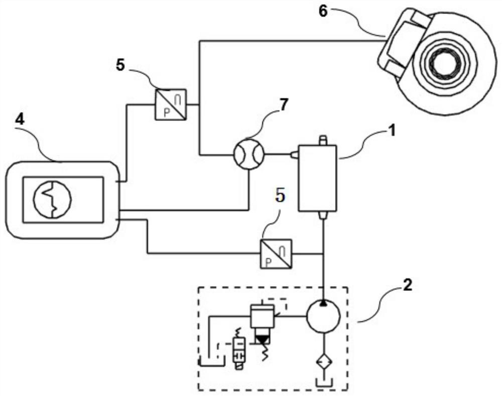
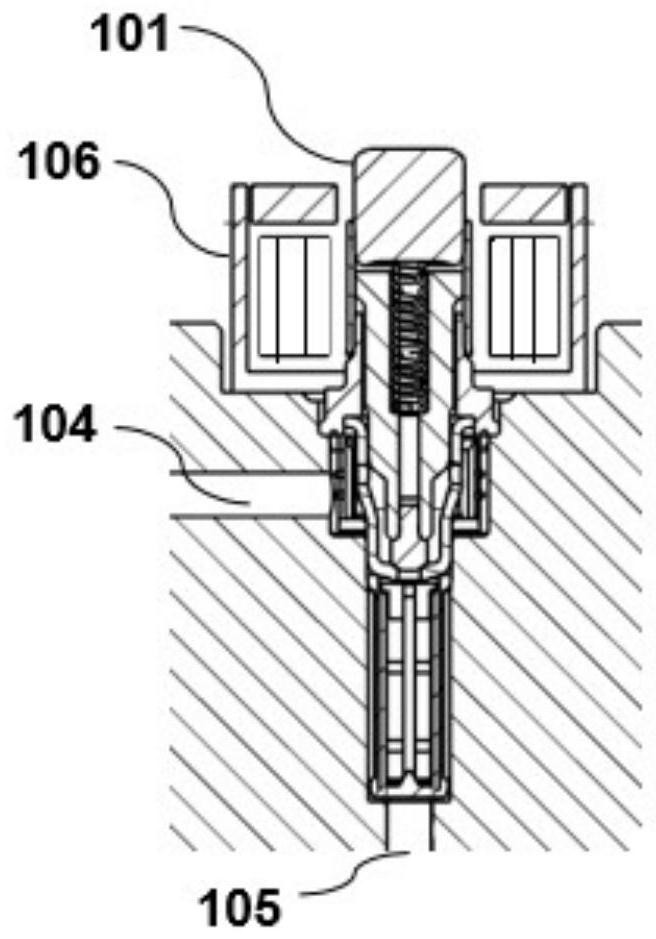
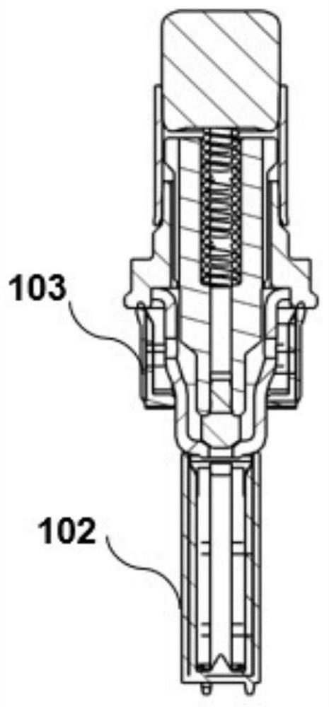
[0017] Such as Figure 1-3 Shown, the present invention relates to a kind of pressure difference flow test device of the electromagnetic valve of automobile compound brake system, including test valve block 1 and pressure source 2, described test valve block 1 is used for installing test solenoid valve, described test valve block 1 is provided with a low-pressure oil port 104 and a high-pressure oil port 105, the pressure source 2 communicates with the high-pr...


PUM


Abstract

The invention discloses a differential pressure flow testing device for an electromagnetic valve of an automobile composite braking system. The device comprises a test valve block and a pressure source, the test valve block is used for mounting a test electromagnetic valve; the test valve block is provided with a low-pressure oil port and a high-pressure oil port; the pressure source is communicated with the high-pressure oil port to provide high-pressure oil for the test valve block; the low-pressure oil port of the test valve block is communicated with a load component, the low-pressure oilport and the high-pressure oil port are respectively connected with a pressure sensor, the low-pressure oil port is further connected with a flow meter, and the flow meter and the pressure sensors arerespectively and electrically connected with an oscilloscope. The flow and pressure difference relation curve generated by the flow of the low-pressure port of the electromagnetic valve along with the pressure change of the high-pressure port can be quickly obtained, and the influence of the difference of the mesh number of the filter screen on the flow and pressure difference curve of the electromagnetic valve can be tested when the same electromagnetic valve structure is adopted.

Description

technical field [0001] The invention relates to the field of auto parts detection, in particular to a pressure difference flow test device for an electromagnetic valve of an automobile composite brake system. Background technique [0002] The solenoid valve is the core component of the actuator of the automobile braking system. Its main function is to control the flow of the braking system to form the pressure of the wheel cylinder. By accurately adjusting the opening and closing time of the solenoid valve, the pressure in the actuator can be established and Release to take control. Solenoid valves in braking systems are generally divided into two categories: normally open solenoid valves and normally closed solenoid valves. In order to accurately control the flow and pressure of the internal pipeline of the brake system, it is necessary to test the flow of the solenoid valve. [0003] The flow characteristics of the solenoid valve mainly depend on the structural character...

Claims


Application Information

Patent Timeline
Patent Type & Authority Applications(China)
IPC IPC(8): G01F1/34
CPCG01F1/34
Inventor 蒋开洪彭小峰万理平阴法国王伟玮王冰
Owner NINGBO TUOPU GROUP CO LTD
Why Eureka
Try Eureka