A capacitance measurement method based on the principle of electrostatic self-excited vibration

A technology of self-excited vibration and capacitance measurement, which is applied in the direction of capacitance measurement, measuring device, and electric variable measurement, can solve the problems of complicated circuit debugging and low measurement resolution, and achieve high resolution, simple test principle and high stability Effect

Active Publication Date: 2022-02-22
BEIHANG UNIV
View PDF13 Cites 0 Cited by
  • Summary
  • Abstract
  • Description
  • Claims
  • Application Information

AI Technical Summary

Problems solved by technology

[0006] Aiming at the problems of complex circuit debugging and low measurement resolution in the existing capacitance measurement technology, the present invention provides a capacitance measurement method based on the principle of electrostatic self-excited vibration, which greatly improves the accuracy of the output electrical signal compared with pure electronic circuit components. resolution

Method used


Image

  • A capacitance measurement method based on the principle of electrostatic self-excited vibration
  • A capacitance measurement method based on the principle of electrostatic self-excited vibration

Examples


Embodiment 1

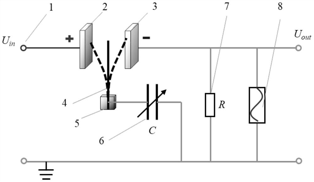
[0028] Embodiment one: if figure 1 As shown, the capacitance measurement method based on the electrostatic self-excited vibration principle provided by the present invention includes a high-voltage DC power supply 1, a positive electrode plate 2, a negative electrode plate 3, a conductive microbeam 4, an insulating support 5, a capacitor to be measured 6, and a sampling resistor 7. Signal collector 8. Wherein, the positive pole of the high-voltage DC power supply 1 is connected to the positive electrode plate 2, and the negative pole is grounded. The conductive microbeam 4 is fixed on the insulating support 5 and placed between the positive electrode plate 2 and the negative electrode plate 3 . One end of the capacitor 6 to be tested is connected to the conductive micro-beam 4 , and the other end is connected to the negative pole of the high-voltage DC power supply 1 (grounded). One end of the sampling resistor 7 is connected to the negative electrode plate 3, and the other ...

Embodiment 2

[0030] Embodiment two: figure 1 The support method of the medium-conducting microbeam 4 adopts the form of simple support at both ends, and other technical features are the same as in the first embodiment.

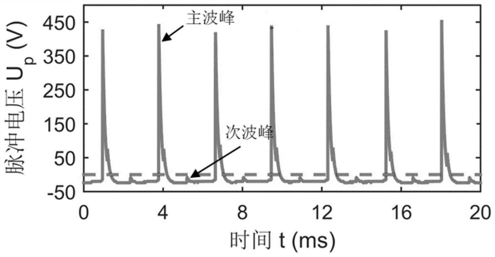
[0031] The pulse voltage signal measured by the capacitance measurement method proposed by the present invention is as follows: figure 2 As shown, when the conductive microbeam 4 collides with the negative electrode plate 3, a main peak of the pulse voltage is generated at both ends of the sampling resistor 7; when the conductive microbeam 4 collides with the positive electrode plate 2, a secondary peak of the pulse voltage is generated at both ends of the sampling resistor 7. Wherein, the size of the capacitor 6 to be tested has a linear relationship with the main peak of the pulse voltage. In this example, the average amplitude of the main peak of the pulse voltage is 484.0V, and the calculated capacitance to be tested is 7.47pF.


PUM

PropertyMeasurementUnit
lengthaaaaaaaaaa
widthaaaaaaaaaa
thicknessaaaaaaaaaa

Abstract

The invention discloses a capacitance measuring method based on the principle of electrostatic self-excited vibration, which comprises a high-voltage DC power supply, positive and negative electrode plates arranged in parallel, conductive microbeams, insulating supports, sampling resistors, capacitance to be measured, and a signal collector. The conductive micro-beams are fixed on the insulating support and placed in the middle of the positive and negative electrode plates. The positive and negative electrode plates are respectively connected to the positive and negative electrodes of the high-voltage DC power supply. One side of the sampling resistor is connected to the negative electrode plate and the other side is grounded. The capacitor to be measured is connected to the Between the root of the conductive microbeam and the negative pole of the power supply. When high-voltage direct current is applied to the positive and negative electrode plates, the conductive microbeams excite self-excited vibrations in the middle of the electrode plates, and the signal collector measures the pulse voltage at both ends of the resistance. The pulse voltage amplitude is linearly related to the capacitance to be measured. The magnitude of the pulse voltage can be calculated to obtain the size of the capacitance to be measured. The capacitance testing method proposed by the invention has simple principle and high measurement precision, and is suitable for measuring tiny capacitance values ​​in the pF order.

Description

technical field [0001] The invention relates to the technical field of capacitance measurement, in particular to a high-precision capacitance measurement method based on the principle of self-excited vibration of microbeams in an electrostatic field. Background technique [0002] Capacitive sensor is a sensing element that converts the measured physical quantity into capacitance change. Because of its simple structure, good dynamic response, high temperature stability and high precision, it is widely used in displacement, angle, vibration, speed, pressure, Composition analysis, medium characteristics and other high-precision measurement occasions. [0003] The measurement of capacitance change is a key factor in determining the measurement accuracy of capacitive sensors. During the working process of the capacitive sensor, the change of the physical quantity to be measured causes the change of the capacitance of the sensing element, and the change of the capacitance is conv...

Claims


Application Information

Patent Timeline
Patent Type & Authority Patents(China)
IPC IPC(8): G01R27/26
CPCG01R27/2605
Inventor 刘志伟闫晓军刘馨怡漆明净竹阳升
Owner BEIHANG UNIV
Why Eureka
Try Eureka