Drawer door body structure and disinfection cabinet

A technology of disinfection cabinet and door body, applied in the field of cabinets, can solve the problem of occupying space of disinfection cabinet and so on

Active Publication Date: 2020-10-20
NINGBO FOTILE KITCHEN WARE CO LTD
View PDF10 Cites 0 Cited by
  • Summary
  • Abstract
  • Description
  • Claims
  • Application Information

AI Technical Summary

Problems solved by technology

However, the chopsticks rack protrudes from the back of the door, occupying the space in the disinfection cabinet

Method used


Image

  • Drawer door body structure and disinfection cabinet
  • Drawer door body structure and disinfection cabinet
  • Drawer door body structure and disinfection cabinet

Examples


Embodiment 2

[0084] This embodiment is a disinfection cabinet using the door structure in Embodiment 1.

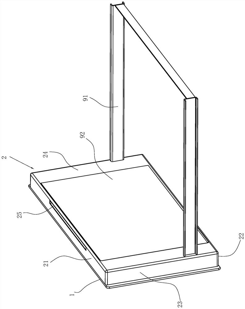
[0085] Such as Figure 12 As shown, the door body structure in Embodiment 1 is used as the door body of the basket of the disinfection cabinet, and is installed on the basket body 91 .

[0086] Corresponding to the position of the chopsticks cage 4, the back plate 24 of the frame body 2 is provided with an irradiation window 29, and transparent quartz glass 92 is installed on this irradiation window 29, so that the UV lamp in the disinfection cabinet liner works. The emitted ultraviolet rays can irradiate on the chopsticks in the chopstick cage 4 through the transparent quartz glass, thereby disinfecting the chopsticks.

[0087] All the other contents are the same as in Example 1.


PUM


Abstract

The invention relates to a drawer door body structure and a disinfection cabinet. The drawer door body structure comprises a panel and a handle arranged on the panel and is characterized in that the drawer door body structure also comprises a frame body, the frame body is connected to the back surface of the panel, and a cavity is defined by the frame body and the panel; a chopstick cage capable of moving up and down under the action of external force is arranged in the cavity, and chopstick holes communicated with the chopstick cage 4 are formed in the frame body; a first elastic piece for enabling the chopstick cage to have an upward moving trend is arranged between the chopstick cage and the bottom plate of the frame body; a groove is formed in the panel, and a handle capable of movingup and down under the action of external force is arranged in the groove; the handle is in driving connection with the grabbing assembly through the transmission assembly, and the grabbing assembly isused for grabbing chopsticks in the chopstick cage so as to take out the chopsticks; the direction limiting mechanism is arranged in the cavity and used for limiting the moving direction of the chopstick box; and the reversing mechanism is arranged in the cavity and is used for changing the limiting direction of the chopstick box by the limiting mechanism.

Description

technical field [0001] The invention relates to the field of cabinets, in particular to a cabinet drawer door body structure and a disinfection cabinet using the structure. Background technique [0002] CN201710867963.5 discloses "A Disinfection Cabinet Based on Smart Home Appliances", which includes a cabinet door and a cabinet body. Placement rack, the chopsticks placement rack is arranged below the PLC control box, a display is arranged on the outer wall of the cabinet door, the PLC control box is electrically connected to the display, and the side wall away from the cabinet door in the cabinet is sequentially A first heat pipe and a second heat pipe are provided, and the first heat pipe and the second heat pipe are arranged parallel to each other. The first heat pipe and the second heat pipe are respectively connected with a first shelf and a second shelf. Both ends of the shelf and the second shelf are fixed on both sides of the cabinet body, the first shelf and the se...

Claims


Application Information

Patent Timeline
Patent Type & Authority Applications(China)
IPC IPC(8): A47B77/04A47B77/18A47B88/90A47B96/20A61L2/10A61L2/26
CPCA47B77/04A47B77/18A47B96/20A61L2/10A61L2/26A61L2202/23A47B88/90
Inventor 陈龙灿王军元
Owner NINGBO FOTILE KITCHEN WARE CO LTD
Why Eureka
Try Eureka