Pump assemblies, compressors and air conditioners

A component and pump body technology, which is applied in the direction of pump components, machines/engines, liquid fuel engines, etc., can solve the problems of insufficient back pressure of the slide vane, separation and leakage between the head of the slide vane and the inner wall of the cylinder, etc., and achieve timely oil supply Effect

Active Publication Date: 2021-07-30
GREE ELECTRIC APPLIANCES INC
View PDF0 Cites 0 Cited by
  • Summary
  • Abstract
  • Description
  • Claims
  • Application Information

AI Technical Summary

Problems solved by technology

[0006] Therefore, the technical problem to be solved in this application is to provide a pump body assembly, a compressor and an air conditioner, so as to solve the problem of insufficient back pressure of the sliding vanes due to untimely oil supply when the existing compressors operate at medium and low frequencies. The head is detached from the inner wall of the cylinder, resulting in leakage, which affects the energy efficiency and reliability of the compressor

Method used


Image

  • Pump assemblies, compressors and air conditioners
  • Pump assemblies, compressors and air conditioners
  • Pump assemblies, compressors and air conditioners

Examples


Embodiment Construction

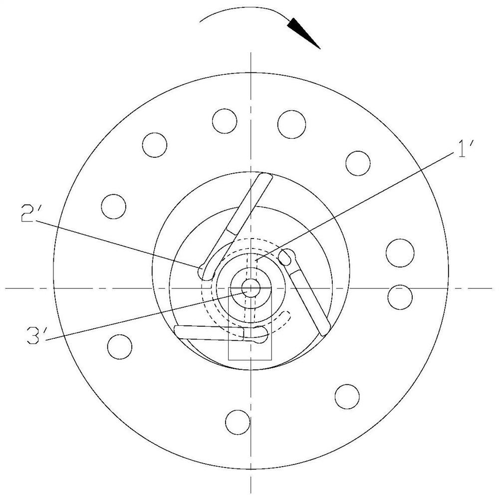
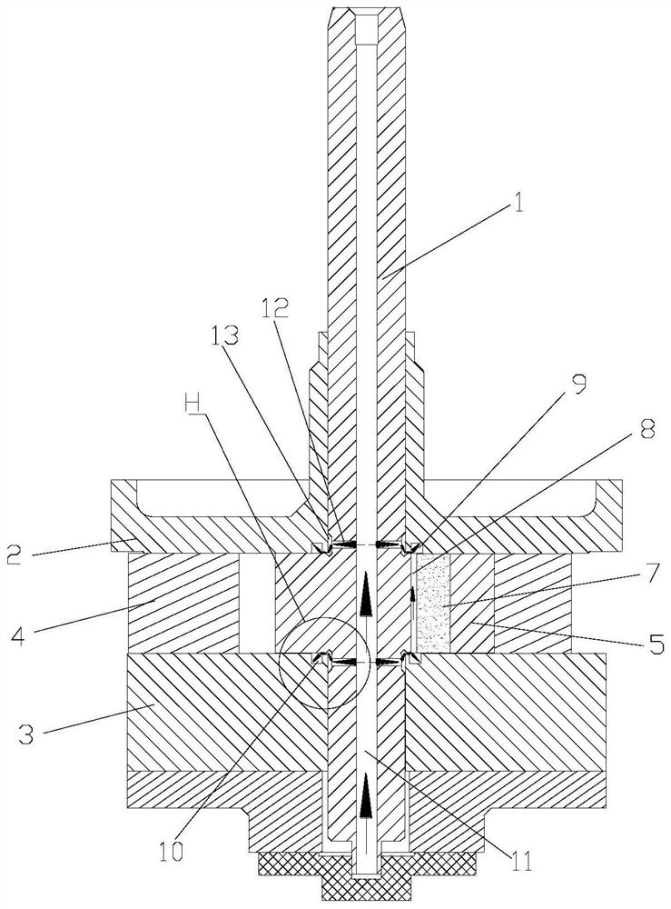
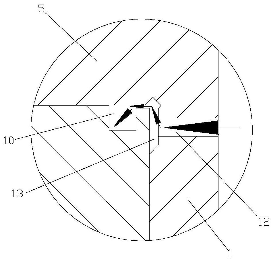
[0028] see in conjunction Figure 2 to Figure 8 As shown, according to the embodiment of the present application, the pump body assembly includes a main shaft 1, an upper flange 2, a lower flange 3, a cylinder 4 and a roller 5, the roller 5 is fixed circumferentially with respect to the main shaft 1, and the roller 5 is provided with There is a sliding piece groove 6, and a sliding piece 7 is slidably arranged in the sliding piece groove 6, the head of the sliding piece 7 abuts against the inner wall of the cylinder 4, and a tail cavity 8 is formed between the tail of the sliding piece 7 and the tail of the sliding piece groove 6 , the upper flange 2 is provided with a first back pressure groove 9 and / or the lower flange 3 is provided with a second back pressure groove 10, the main shaft 1 is provided with a connected central hole 11 and a side hole 12, and the tail chamber 8 The back pressure groove communicates with the side hole 12. In the section perpendicular to the centr...


PUM


Abstract

The application provides a pump body assembly, a compressor and an air conditioner. The pump body assembly includes a main shaft, an upper flange, a lower flange, a cylinder and rollers. The rollers are fixed circumferentially relative to the main shaft. A slide groove is arranged on the roller, and a slide is provided for sliding in the slide groove. The head of the cylinder abuts against the inner wall of the cylinder, a tail cavity is formed between the tail of the slide vane and the tail of the slide vane groove, the upper flange is provided with a first back pressure groove and / or the lower flange is provided with a second back pressure The main shaft is provided with a central hole and a side hole, and the tail cavity communicates with the side hole through the back pressure groove. In the section perpendicular to the central axis of the main shaft, each tail cavity is correspondingly provided with at least one side hole, and the tail cavity is located at the On the extension line of the center line of the side hole corresponding to the tail cavity. According to the pump body assembly of the present application, it can solve the problem that when the existing compressor is running at medium and low frequencies, the back pressure of the sliding vane is insufficient due to untimely oil supply, and the head of the sliding vane is separated from the inner wall of the cylinder, resulting in leakage and affecting the compressor. Issues of energy efficiency and reliability.

Description

technical field [0001] The present application relates to the technical field of air conditioning, in particular to a pump body assembly, a compressor and an air conditioner. Background technique [0002] In the existing rotary vane compressor, in order to ensure that the sliding vane can be extended smoothly during operation, a back pressure chamber is generally provided at the tail of the sliding vane (sliding vane tail cavity formed by the sliding vane and the main shaft sliding vane groove + the back pressure of the upper flange Groove + lower flange back pressure groove), and introduce high-pressure oil from the oil pool to provide power for the back of the slide vane, which is used to overcome the gas pressure and friction in the front and rear chambers of the slide vane head, to ensure that the compressor runs smoothly during the entire operation process. The slice head is always in contact with the inside of the cylinder. [0003] The oil under the back pressure of ...

Claims


Application Information

Patent Timeline
Patent Type & Authority Patents(China)
IPC IPC(8): F04C18/344F04C29/00
CPCF04C18/3445F04C29/00
Inventor 吴飞万鹏凯扶峥苏永强邹鹏任丽萍
Owner GREE ELECTRIC APPLIANCES INC
Why Eureka
Try Eureka