fuel supply holding valve

A fuel supply and maintenance valve technology, which is applied in the direction of fuel injection devices, charging systems, machines/engines, etc., can solve the problem that the air in the oil return channel cannot be completely emptied, and the fuel replenishment and back pressure maintenance cannot be realized at the same time. Realize problems such as oil return back pressure maintenance, and achieve the effect of saving energy loss, fewer parts and less space

Active Publication Date: 2020-07-17
CHINA FIRST AUTOMOBILE
View PDF10 Cites 0 Cited by
  • Summary
  • Abstract
  • Description
  • Claims
  • Application Information

AI Technical Summary

Problems solved by technology

[0010] Among the above-mentioned patents for oil return back pressure maintenance, patent CN102062244 A and patent CN105156388 A only have the function of oil return back pressure maintenance, respectively, and do not have the function of amplifying piston replenishment, while patents CN1864023 A and CN103075382 A realize The function only has the function of replenishing oil to the enlarged piston, and cannot realize the function of maintaining the back pressure of the oil return at the same time
The above four patents only realize the function of back pressure maintenance or oil replenishment through the check valve, and cannot realize the functions of oil replenishment and back pressure maintenance at the same time
[0011] In the current piezoelectric common rail system, fuel is generally added to the oil return channel of the piezoelectric injector by disassembling the oil pipe, which is inefficient and troublesome to operate, and it is impossible to ensure that the air in the oil return channel is completely emptied, and there will be Fuel leakage is dangerous to a certain extent; in addition, the amplified piston piezoelectric fuel injector needs to maintain a certain back pressure during the working process. The current solution is to use a one-way valve to adjust and maintain the pressure. The method realizes pressure maintenance, but the operation of adjusting the back pressure is complicated, and the oil return is small and the pressure accumulation is slow, and the injector needs to operate at low pressure for a long period of time to work normally

Method used


Image

  • fuel supply holding valve
  • fuel supply holding valve
  • fuel supply holding valve

Examples


Embodiment Construction

[0061] The present invention will be further described below in conjunction with specific drawings.

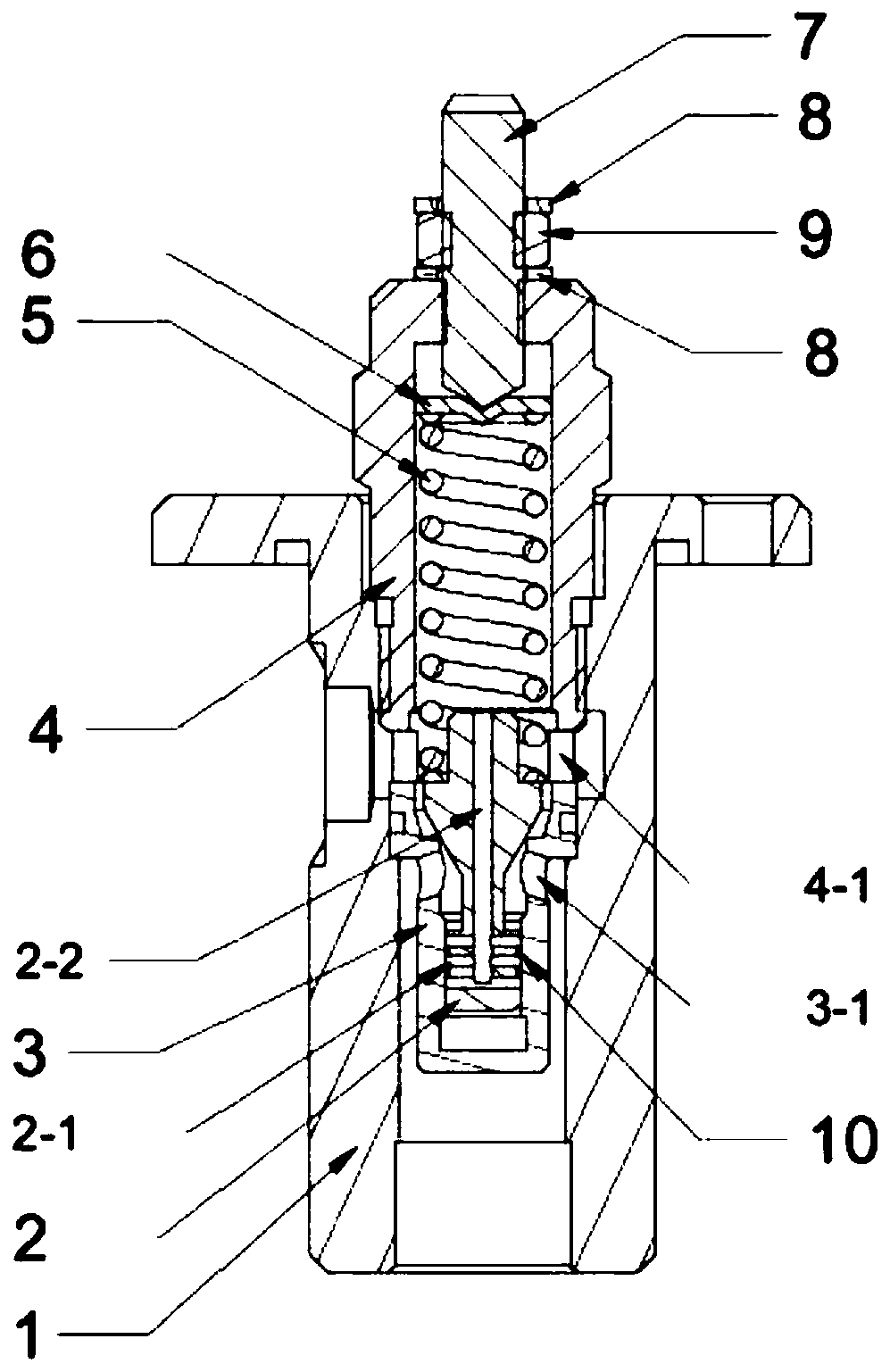
[0062] Such as Figure 5 As shown, the fuel supply maintenance valve of the present invention includes a casing 1 and an oil return base 6. The casing 1 is provided with an injector oil return port A and a pressure gauge port C, and the injector oil return port A and pressure The interface C of the meter end is connected with the inner cavity of the shell 1, and the oil supply spring 2 is arranged in the inner cavity of the shell 1, and the sealing valve 3 is installed in the oil supply spring 2; the oil return base 6 has a middle hole, and the oil return base 6 An adjustment valve 9 is set in the middle hole of the base 6, and an O-ring 5 is used to seal between the adjustment valve 9 and the oil return base 6; an oil return spring 4 and an orifice plate 10 are installed on the upper end of the adjustment valve 9, 9 is provided with an adjustment rod 7 on the bottom of the a...


PUM


Abstract

The invention relates to a fuel supply maintaining valve. The maintaining valve comprises a shell and an oil return base. The maintaining valve is characterized in that an oil atomizer oil return endconnector and a pressure gauge end connector are arranged on the shell, the oil atomizer oil return end connector and the pressure gauge end connector both communicate with an inner cavity of the shell, an oil supplementing spring is arranged in the inner cavity of the shell, and a sealing valve is installed in the oil supplementing spring; the oil return base is provided with a middle hole, an adjusting valve is arranged in the middle hole of the oil return base, an oil return spring and a hole plate are installed at the upper end of the adjusting valve, and an adjusting rod is arranged at the bottom of the adjusting valve; the lower end of the shell is screwed and assembled with the upper end of the oil return base, and the lower end of the sealing valve of the inner cavity of the shellis in contact with the hole plate located at the upper end of the middle hole of the oil return base so as to realize sealing; and an oil tank end connector is arranged on the oil return base, and theoil tank end connector communicates with the middle hole of the oil return base. According to the fuel supply maintaining valve, the bidirectional pressure maintaining can be realized, oil return back pressure can be kept, furthermore, oil supplementing operation of an amplifying piston cavity can be realized, and working efficiency and system stability are greatly improved.

Description

technical field [0001] The invention relates to a fuel supply maintaining valve, in particular to a fuel supply maintaining valve suitable for a common rail system with back pressure requirements. Background technique [0002] With the upgrading of emission regulations, diesel engines using high-pressure common rail fuel injection technology are widely used. With the further increase of injection pressure and injection times, higher requirements are put forward for injectors. Appropriate oil return back pressure of the common rail injector is conducive to improving the stability of the fuel injection, and the use of piezoelectric injectors with fast response and high reliability is one of the means to achieve high-pressure multiple injections. In current piezoelectric injectors, an amplified piston structure is often used to achieve displacement amplification, thereby reducing the requirements on the actuator. Since the amplifying mechanism needs hydraulic oil as the transm...

Claims


Application Information

Patent Timeline
Patent Type & Authority Patents(China)
IPC IPC(8): F02M63/00
CPCF02M63/0012
Inventor 张恒平毛立伟吴松臧娈
Owner CHINA FIRST AUTOMOBILE
Why Eureka
Try Eureka