

Scroll compressor
A scroll compressor and scroll technology, applied in the field of scroll compressors, can solve problems such as performance deterioration and leakage
- Summary
- Abstract
- Description
- Claims
- Application Information
AI Technical Summary
Problems solved by technology
Method used
Image

Examples
Embodiment 1
[0212] Hereinafter, embodiments of the present invention will be described with reference to the drawings. In addition, the present invention is not limited to these embodiments.
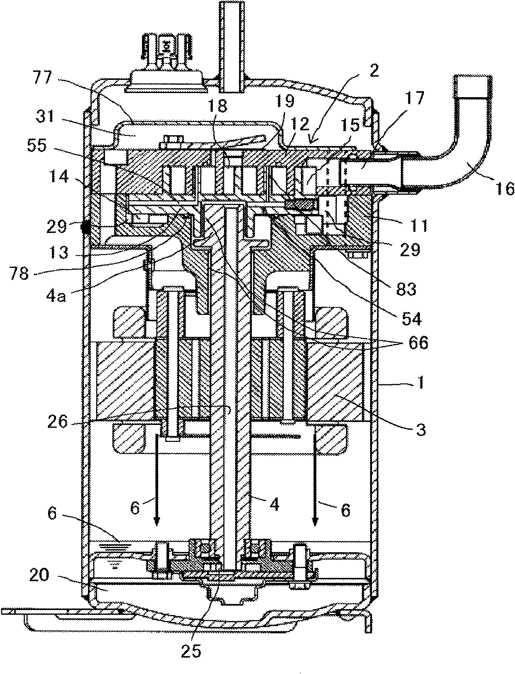
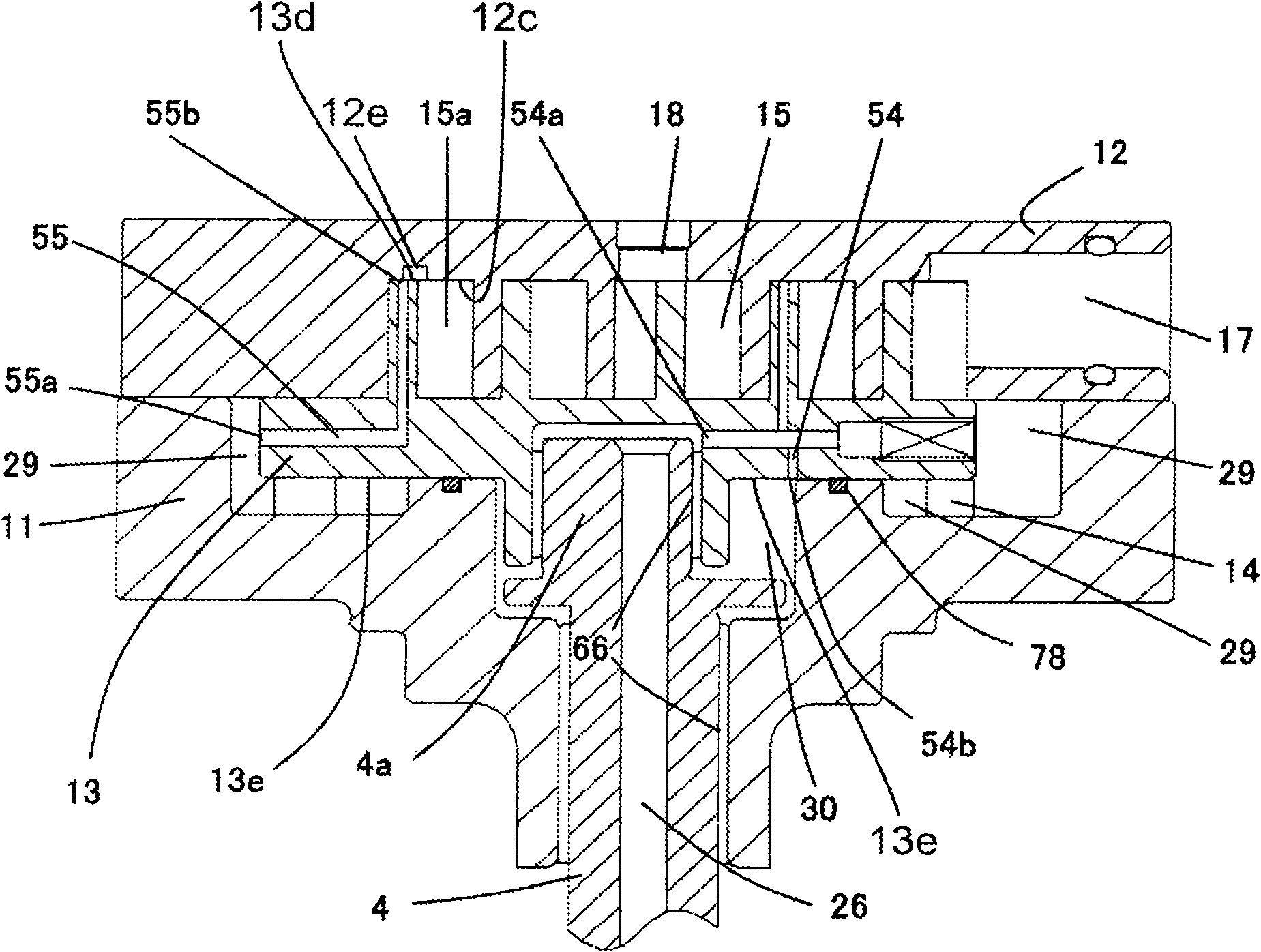
[0213] The first embodiment of the present invention will be described. figure 1 Is a longitudinal sectional view of the scroll compressor in the first embodiment of the present invention, figure 2 Yes figure 1 Sectional view of the compression mechanism of the scroll compressor. Next, the structure, operation, and function of the scroll compressor of the first embodiment will be described.
[0214] Such as figure 1 , figure 2 As shown, the scroll compressor of the present embodiment is composed of an airtight container 1, a compression mechanism 2 provided in the airtight container 1, a motor part 3, and an oil reservoir 20.
[0215] The main bearing part 11 of the crankshaft 4 fixed by welding and thermo-compression fitting in the airtight container 1 and the fixed scroll 12 fixed on the main beari...
Embodiment 2
[0253] The second embodiment of the present invention will be described. Figure 7 It is a cross-sectional view of the compression mechanism of the scroll compressor in the second embodiment of the present invention. In this embodiment, the invention part that is different from the embodiment 1 will be described. That is, in Figure 7 In, for and figure 2 The same components are given the same symbols, and their descriptions are omitted.
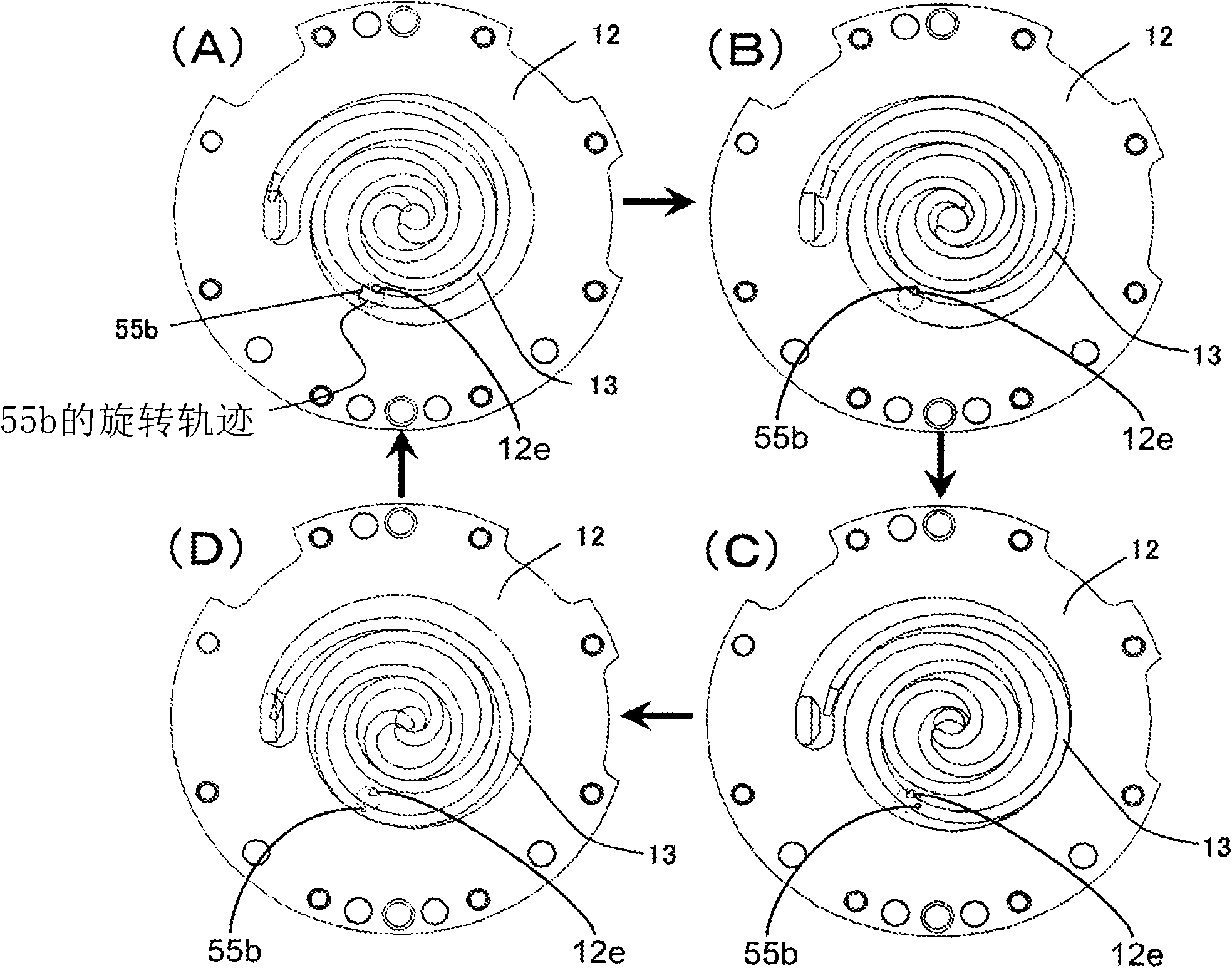
[0254] Such as Figure 7 As shown, in the scroll compressor of this embodiment, the second path 56 is constituted by a second control path that passes from the back pressure chamber 29 through the inside of the orbiting scroll 13 and then communicates with the thrust surface 13f of the orbiting scroll 13. Furthermore, the second control path opens intermittently in the scroll tooth groove 12g of the fixed scroll 12 according to the rotational movement.
[0255] Picture 8 Is a cross-sectional view of the orbiting scroll 13 and the fixed scroll ...
Embodiment 3
[0265] The third embodiment of the present invention will be described. Picture 9 Is a longitudinal sectional view of the scroll compression mechanism in the third embodiment of the present invention, Picture 10 Yes Picture 9 Sectional view of the compression mechanism of the scroll compressor, Picture 11 Yes Picture 10 A cross-sectional view of the fixed scroll and the orbiting scroll of the compression mechanism in a meshing state.
[0266] Such as Picture 9 As shown, in the scroll compressor of this embodiment, the main bearing part 11 of the crankshaft 4 fixed by welding and hot press fitting in the airtight container 1 and the fixed scroll 12 fixed with bolts on the main bearing part 11 In between, the orbiting scroll 13 meshing with the fixed scroll 12 is sandwiched to constitute a scroll compression mechanism 2. Furthermore, a rotation restricting mechanism 14 is provided between the orbiting scroll 13 and the main bearing member 11, and the rotation restricting mecha...
PUM
 Abstract
Description
Claims
Application Information