Tightening chain fixing mechanism

A fixing mechanism and fixing seat technology, which is applied in the direction of friction clamping detachable fasteners, connecting components, supporting machines, etc., can solve the problems of limited installation space of fixed brackets, insufficient tightening force, fixed installation length, etc.

Pending Publication Date: 2020-10-20
深圳市衡流科技有限公司
View PDF0 Cites 0 Cited by
  • Summary
  • Abstract
  • Description
  • Claims
  • Application Information

AI Technical Summary

Problems solved by technology

[0007] The invention provides a tightening chain fixing mechanism, which aims to solve the problems of limited installation space, fixed installation length and insufficient tightening force of existing fixing brackets.

Method used


Image

  • Tightening chain fixing mechanism
  • Tightening chain fixing mechanism
  • Tightening chain fixing mechanism

Examples


Embodiment 1

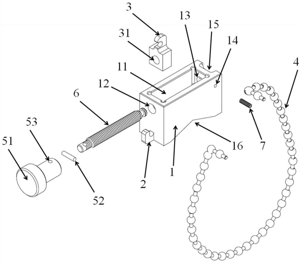
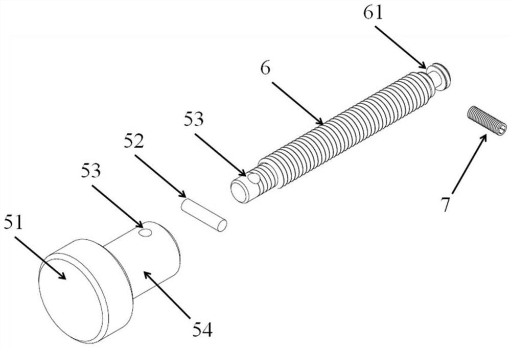
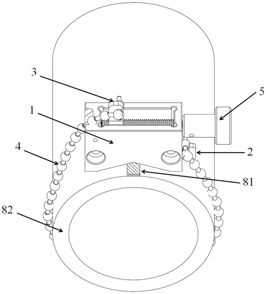
[0024] like Figure 1 to Figure 3 As shown, a tightening chain fixing mechanism of the present invention includes a fixed seat 1, a fixed hook 2, a movable hook 3, a tightening chain 4, a driving part 5, and a directional rod 6, and the fixed hook 2 is fixedly connected to the fixed On the seat 1, the fixed seat 1 is provided with a guide groove 11, the directional rod 6 is arranged in the guide groove 11, the movable hook 3 is connected on the directional rod 6, one end of the tightening chain 4 is stuck on the fixed hook 2, and the other One end is stuck on the movable hook 3 after bypassing the object to be fixed, the driving part 5 is connected to the directional rod 6 and drives the movable hook 3 to move along the guide groove 11 through the directional rod 6, and the movable hook 3 is close to the fixed hook 2 The direction of moving makes tightening chain 4 taut.

[0025] The tightening chain fixing mechanism includes a directional rod limit post 7, a directional rod ...

Embodiment 2

[0032] like Figure 1 to Figure 3 As shown, on the basis of the first embodiment, a guide rail can be provided in the guide groove 11, and the movable hook 3 is first slidably connected to the guide rail. The threaded hole 31 is cooperatively connected with the movable hook 3, and the rotating screw rod drives the movable hook 3 to move directionally along the guide rail. The design of the guide rail allows the movable hook 3 to move on the directional track of the guide rail, which is also a kind of positioning for the movable hook. When assembling, the screw rod is directly screwed into the threaded hole 31 of the movable hook 3 and fixed in the guide groove within 11.

[0033] As another embodiment, the guide groove 11 can also be entirely replaced with a guide rail structure. There is a movable hook 3 on the guide rail, and a screw rod passes through the middle of the movable hook 3. Rotating the screw rod realizes the orientation of the movable hook 3 along the guide rail....

Embodiment 3

[0035] On the basis of Embodiments 1 and 2, the driving part 5 can be replaced by a cylinder or a hydraulic cylinder, and the positioning rod 6 can be replaced by a cylinder connecting rod or a hydraulic cylinder connecting rod. The cylinder drives the movable hook 3 along the guide through the cylinder connecting rod. The groove 11 moves in a direction, or the hydraulic cylinder drives the movable hook 3 to move in a direction along the guide groove 11 through the connecting rod of the hydraulic cylinder. Cooperating with the guide groove 11 or the guide rail, the directional movement of the movable hook 3 is directly driven by the cylinder or hydraulic cylinder, and the tension of the tightening chain 4 can also be well controlled, and it can be used with automation equipment or realize remote electronic control.

[0036] The driving mechanism, positioning rod 6, and guide groove 11 of the present invention are not limited to the schemes described, as long as the structure th...


PUM


Abstract

The invention relates to the field of pipeline installation brakes, in particular to a tightening chain fixing mechanism. The tightening chain fixing mechanism comprises a fixing seat, a fixed hook, amovable hook, a tightening chain, a driving part and an oriented rod; the fixed hook is fixedly connected to the fixing seat, the fixing seat is provided with a guide groove, and the oriented rod isarranged in the guiding groove; the movable hook is connected to the oriented rod; one end of the tightening chain is clamped to the fixed hook, and the other end of the tightening chain is clamped tothe movable hook after passing through a to-be-fixed object; the driving part is connected with the oriented rod and drives the movable hook to do oriented motion along the guide groove through the oriented rod, and the movable hook moves in the direction close to the fixed hook to enable the tightening chain to be tightened. The fixing mechanism can conduct fixing operation easily without assisting of any auxiliary tool, is adjustable in fixing force, high in fixing flexibility, capable of adapting to various different sizes of fixing surfaces, high in fixing firmness, high in adaptive capacity for uneven fixing surfaces, and capable of conveniently clamping and putting various shapes and sizes of objects and being applied to working condition where the operation space of a fixing position is small.

Description

technical field [0001] The invention relates to the field of pipe installation brackets, in particular to a tightening chain fixing mechanism. Background technique [0002] The existing pipe installation bracket products include: saddle type fixer, pipe tie, cable tie, and retractable tie. These mounting brackets have the following problems: [0003] 1. Defects of the saddle-shaped fixer: the overall height is large, which is not suitable for narrow operating space applications; the crossbar with the hook is easy to bend and deform after repeated use, and the durability is insufficient; the support point is not stable on uneven surfaces , the tightening is unreliable; [0004] 2. Tube binding defects: fixed length, complex splicing; difficult locking operation; [0005] 3. Tie defects: insufficient tightening force; [0006] 4. Defects of the retractable belt: easy to age, poor acid and alkali resistance of the material, not suitable for outdoor and acid and alkali corro...

Claims


Application Information

Patent Timeline
Patent Type & Authority Applications(China)
IPC IPC(8): F16M13/02F16B2/26
CPCF16B2/26F16M13/02
Inventor 廖琼
Owner 深圳市衡流科技有限公司
Why Eureka
Try Eureka