Orthogonal point laser double-measuring-head pose calibration test piece

A technology of pose calibration and dual probes, which is applied in the direction of measuring devices, optical devices, instruments, etc., can solve problems such as the inability to apply the measurement scene of the workpiece to be measured, the error of system accuracy, and the inability to reflect the calibration error of the origin of the probe.

Pending Publication Date: 2020-10-20
SICHUAN UNIV
View PDF1 Cites 6 Cited by
  • Summary
  • Abstract
  • Description
  • Claims
  • Application Information

AI Technical Summary

Problems solved by technology

[0003] For single-probe pose calibration parts, during the measurement process, it can only meet the calibration work of the surrounding measurement coordinate system or the top measurement coordinate system, and cannot be calibrated at the same time, and the detection efficiency of the workpiece is significantly reduced
[0004] The patent CN201920346069 can only calibrate the three-coordinate detection device of a single laser probe, which cannot be applied in the measurement scene where the top feature surface detection of the workpiece to be measured is required; it has no clamping surface fixed in the detection device, and during the calibration process It will introduce additional system accuracy errors; it has no inspection features of the origin after calibration of the probe coordinate system, so it cannot reflect the calibration error of the probe origin

Method used


Image

  • Orthogonal point laser double-measuring-head pose calibration test piece
  • Orthogonal point laser double-measuring-head pose calibration test piece
  • Orthogonal point laser double-measuring-head pose calibration test piece

Examples


Embodiment Construction

[0015] Preferred embodiments of the present invention are described in detail below in conjunction with accompanying drawings;

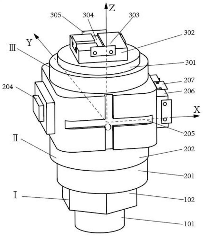
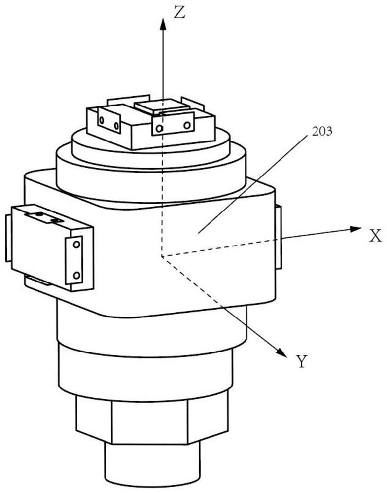
[0016] An orthogonal-point laser double-probe pose calibration test piece is characterized in that it includes a clamping shaft section (I), a horizontal probe calibration shaft section (II), and a vertical probe calibration shaft section (III).

[0017] The clamping shaft section (I) is located at the end of the calibration test piece in the -Z direction, and the clamping shaft section (I) includes a positioning cylindrical surface (101) and a clamping prism surface (102); the axis of the positioning cylindrical surface (101) Coincident with the Z axis of the test piece coordinate system, the distance between its end surface and the XOY reference plane of the test piece coordinate system is a known fixed value; the clamping prism surface (102) is the suction surface where the calibration test piece is fixed on the detection device, and its The axis ...


PUM


Abstract

The invention discloses an orthogonal point laser double-measuring-head pose calibration test piece, which comprises three shaft sections: a clamping shaft section, a horizontal measuring head calibration shaft section and a vertical measuring head calibration shaft section; the clamping shaft section comprises a clamping prism surface and a positioning cylindrical surface; the horizontal measuring head calibration shaft section comprises a calibration cylindrical surface, a calibration eccentric cylindrical surface, and a peripheral alignment plane, a boss type stepped surface, a cross-shapedgroove and a peripheral calibration boss which are distributed according to a calibration station sequence; the vertical measuring head calibration shaft section comprises a circular ring type stepped surface, a top calibration boss, a top alignment plane and a T-shaped groove; in the calibration process, the test piece can satisfy calibration and calibration of the horizontal measuring head andthe vertical measuring head in an orthogonal coordinate system; compared with a single-measuring-head pose calibration test piece, the test piece can effectively improve the measurement range, and reduces pitching and deflection errors in a point laser measuring head installation process and calibration errors of coordinate systems of the two measuring heads by using multiple characteristic surfaces for calibration.

Description

technical field [0001] The invention relates to a calibration test piece of a non-contact three-coordinate detection device, in particular to a pose calibration test piece of an orthogonal point laser double measuring head. Background technique [0002] When the three-coordinate detection device measures the workpiece for the first time, it is necessary to calibrate the accuracy of the three-coordinate detection device. The accuracy of the calibration test piece directly affects the system accuracy of the measurement coordinate system of the three-coordinate detection device; the traditional gantry-type three-coordinate detection device adopts the contact measurement method , using a standard sphere or standard cylinder for calibration, and in the point laser three-coordinate detection device, the application of this calibration specimen effectively suppresses the influence of the depth of field error and inclination error on the calibration accuracy in laser triangulation, a...

Claims


Application Information

Patent Timeline
Patent Type & Authority Applications(China)
IPC IPC(8): G01B11/00
CPCG01B11/007
Inventor 陈珂胡鑫汪永超
Owner SICHUAN UNIV
Why Eureka
Try Eureka