

External adjustable inductance demagnetization detection and power detection circuit
A technology of power detection circuit and discharge circuit, which is applied in the direction of measuring electric power, magnetic performance measurement, electric vehicles, etc., and can solve the problem of different rising rates of inductive current in switching power supplies
Pending Publication Date: 2020-10-20
SHENZHEN FM ELECTRONICS GRP CO LTD
View PDF0 Cites 0 Cited by
- Summary
- Abstract
- Description
- Claims
- Application Information
AI Technical Summary
Problems solved by technology
At the same time, in the case of high input voltage and low input voltage, the switching power supply inductor current rise rate is different
Method used
View moreImage
Smart ImageViewing Examples


Examples
Embodiment
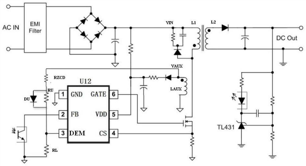
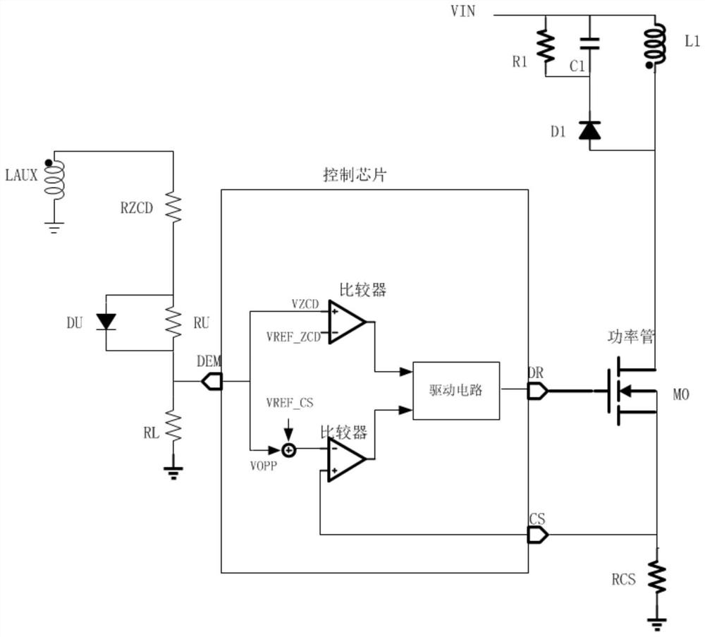
[0024] An externally adjustable inductance demagnetization detection and power detection circuit, see figure 1 , 2 , including discharge circuit, power tube M0, inductance LAUX and voltage divider branch;
[0025] The VIN voltage is connected to the drain of the power tube M0 and the primary inductance L1 through the discharge circuit, and the VIN voltage is obtained from the AC mains after rectification and filtering; the gate of the power tube M0 is connected to the drive terminal of the switching power supply control chip (which is figure 1 Middle GATE terminal), the source of the power tube M0 is grounded through the resistor RCS, and connected to the current detection terminal of the switching power supply control chip;
Login to View More PUM
 Abstract
The invention provides an external adjustable inductor demagnetization detection and power detection circuit. The external adjustable inductor demagnetization detection and power detection circuit comprises a discharge circuit, a power tube M0, an inductor LAUX and a voltage division branch. A VIN voltage is connected to the drain electrode of the power tube M0 and a main-stage inductor L1 throughthe discharge circuit; a gate electrode of the power tube M0 is connected to a driving terminal of a switching power supply control chip, and a source electrode of the power tube M0 is grounded through a resistor RCS and is connected to a current detection terminal of the switching power supply control chip; the inductor LAUX is grounded through the voltage division branch, and a tap of the voltage division branch is connected to a detection terminal of the switching power supply control chip; and the voltage division branch provides different voltages for the detection terminal of the switching power supply control chip. The circuit can provide an ideal compensation voltage for a switching power supply system, output overpower points of the switching power supply system are kept consistent under the conditions of high input voltage and low input voltage, and the application flexibility of a chip is greatly improved.
Description
technical field [0001] The invention belongs to the technical field of electronic circuits, and in particular relates to an externally adjustable inductance demagnetization detection and power detection circuit. Background technique [0002] In the switching power supply system, due to the time delay between the action of the overcurrent protection module of the switching power supply system and the shutdown of the output control power MOS tube, the current of the power MOS tube will continue to rise after reaching the internally set threshold. At the same time, in the case of high input voltage and low input voltage, the rate of rise of the inductor current of the switching power supply is different. When the input voltage is high, the current of the power switching tube rises faster, resulting in a higher output overpower point of the switching power supply under the condition of high input voltage than that under the condition of low input voltage. Contents of the inven...
Claims
Login to View More Application Information
Patent Timeline
 IPC IPC(8): G01R33/12G01R21/00
CPCG01R21/00G01R33/12
Inventor 张敏李科举
Owner SHENZHEN FM ELECTRONICS GRP CO LTD