A wireless signal receiver with anti-theft function
A wireless signal and receiver technology, applied in the direction of cooling/ventilation/heating transformation, electrical equipment casing/cabinet/drawer, casing/cabinet/drawer components, etc., can solve property loss and affect the normal operation of network equipment And other issues
- Summary
- Abstract
- Description
- Claims
- Application Information
AI Technical Summary
Problems solved by technology
Method used
Image
Examples
Embodiment 1
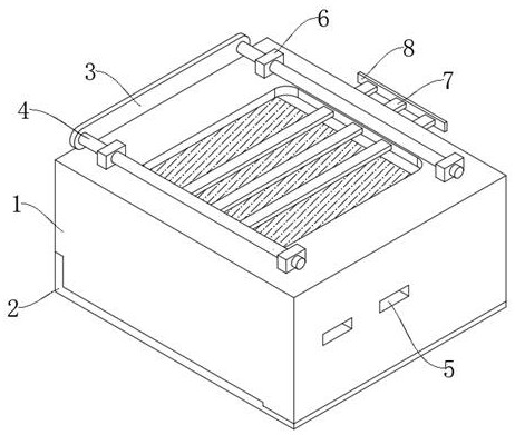
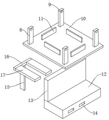
[0030] see Figure 1-2 , a wireless signal receiver with anti-theft function, comprising an upper fixing base 1 and a lower fixing base 2, the upper fixing base 1 is movably connected with a wireless signal receiver body, and the upper fixing base 1 is movably connected with a support plate 10, The four sides of the upper side of the supporting plate 10 are fixedly connected with clamping plates 11, and the wireless signal receiver body is movably clamped in the four clamping plates 11; One end of the upper side of 12 is fixedly connected, and two sockets B14 are opened inside one side of the card holder 12; the socket B14 is matched with an extension guide rod 17, and the end of the extension guide rod 17 runs through the fixing hole 5 on the side wall of the upper fixing seat 1, The other ends of the two extension guide rods 17 are fixedly connected through the second fixed rod 16, and the center of the lower side of the second fixed rod 16 is fixedly connected with a guide ...
Embodiment 2
[0034] see Figure 3-4 , based on Example 1, the difference is that:
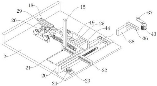
[0035] One end of the upper side of the lower fixed seat 2 is fixedly connected with a forward frame 20, and one end of the advanced frame 20 is fixedly connected with a guide rail frame 19, and the bottom of the guide rail frame 19 is fixedly connected with the upper wall of the lower fixed seat 2; the guide rail frame 19 communicates with the forward frame 20 , a plurality of advancing blocks 44 are slidably connected inside the rail frame 19;
[0036] An extrusion block 25 is slidably connected inside the guide rail frame 19, and the extrusion block 25 is located at the innermost side of the guide rail frame 19; a drive plate 38 is slidably connected to the opening at the end of the forward frame 20, and the center of the drive plate 38 is fixedly connected with a drive block through a connecting rod. 36, one end of the driving part 37 is movably connected to the sliding frame at the center of the drivi...
Embodiment 3
[0040] see Figure 4-5 , based on Embodiment 1 and 2, the difference is that:
[0041] One side of the driving rack 22 is provided with a forward tooth groove 33, and the forward tooth groove 33 is meshed with the driving wheel 24. The lower end of the axis of the driving wheel 24 runs through the mounting plate 23 and is fixedly connected to the upper end of the output shaft of the motor D45. The motor D45 is fixed to the lower The seat 2 is fixedly connected; the center of the other side of the driving rack 22 is movably connected with a spring B39, and the other end of the spring B39 is fixedly connected to the connector 35, and the connector 35 is fixedly connected to the outer wall of one end of the forward frame 20;
[0042] Rail frame 19 one side walls are threadedly connected with drive screw rod 30, on the drive screw rod 30 is movably connected with group dividing plate 34, group dividing plate 34 both sides and guide rail frame 19 both sides are all fixedly connecte...
PUM
 Abstract
Description
Claims
Application Information
 - R&D
- Intellectual Property
- Life Sciences
- Materials
- Tech Scout
- Unparalleled Data Quality
- Higher Quality Content
- 60% Fewer Hallucinations
Browse by: Latest US Patents, China's latest patents, Technical Efficacy Thesaurus, Application Domain, Technology Topic, Popular Technical Reports.
© 2025 PatSnap. All rights reserved.Legal|Privacy policy|Modern Slavery Act Transparency Statement|Sitemap|About US| Contact US: help@patsnap.com


