Environment-friendly industrial waste gas purification and cyclic utilization equipment

An industrial waste gas and environmental protection technology, which is applied in the direction of lighting and heating equipment, waste heat treatment, process efficiency improvement, etc., can solve the problems of increasing device manufacturing costs and reducing heat energy recovery benefits, etc.

Inactive Publication Date: 2020-10-23
刘景容
View PDF0 Cites 4 Cited by
  • Summary
  • Abstract
  • Description
  • Claims
  • Application Information

AI Technical Summary

Problems solved by technology

[0004] In order to make up for the deficiencies of the existing technology, most of the industrial waste gas purification and recycling devices in the prior art need an external power source to operate. On the one hand, the addition of an external power source increases the manufacturing

Method used


Image

  • Environment-friendly industrial waste gas purification and cyclic utilization equipment
  • Environment-friendly industrial waste gas purification and cyclic utilization equipment
  • Environment-friendly industrial waste gas purification and cyclic utilization equipment

Examples


Embodiment approach

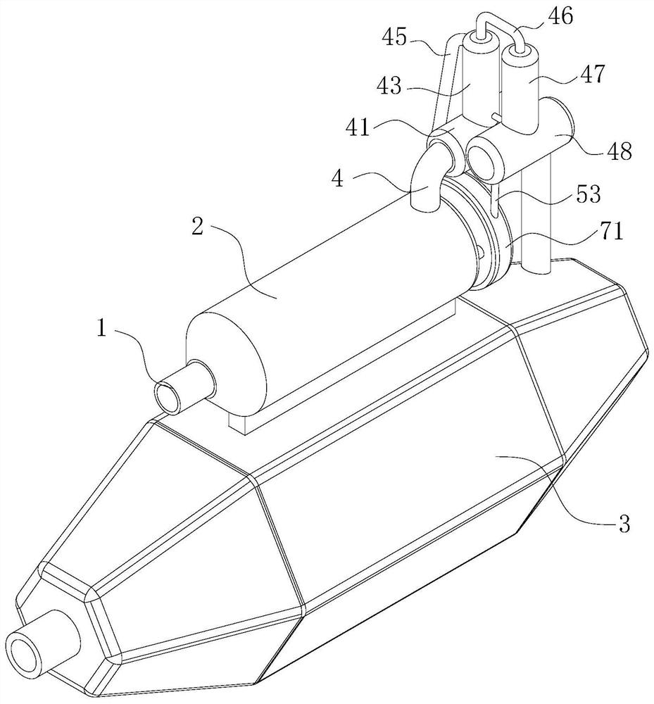
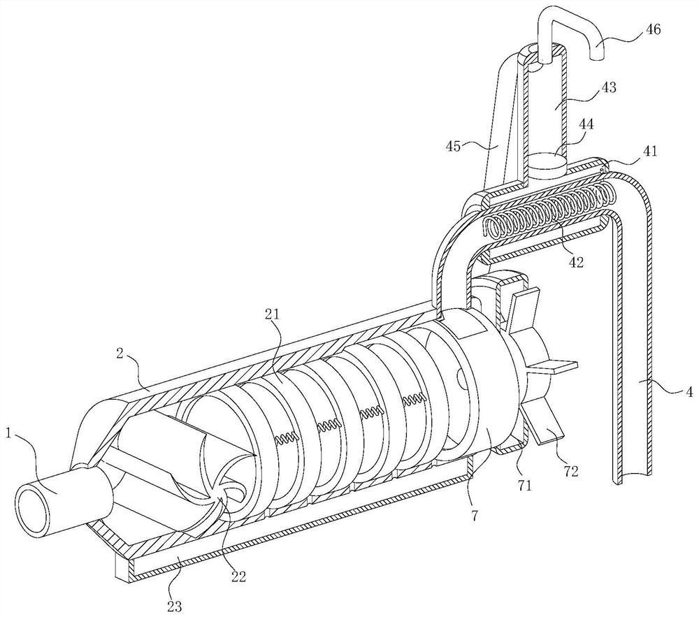
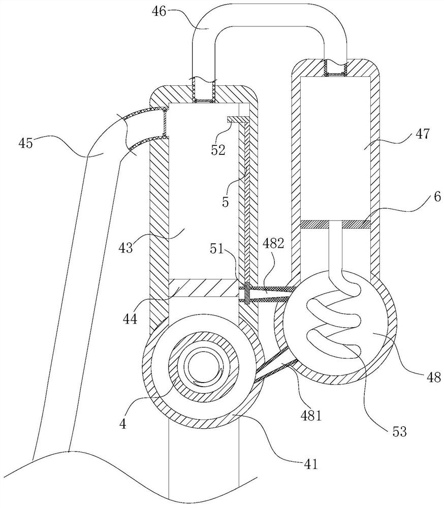
[0025] As an embodiment of the present invention, the end of the dust removal chamber 2 away from the intake pipe 1 is rotatably connected with a rotating shaft; the rotating shaft extends to the outside of the dust removal chamber 2; Rotating ring 7; the rotating ring 7 fits the inner diameter of the dust removal chamber 2; the side wall of the rotating ring 7 is provided with symmetrically designed first through grooves; the two first through grooves occupy three thirds of the rotating ring 7 circumference One; the end of the dust removal chamber 2 away from the intake pipe 1 is fixedly connected with a transmission chamber 71 through a guide rod; the rotating shaft extends into the transmission chamber 71; the rotating shaft is located in the transmission chamber 71 and is fixedly connected with a rotating fan blade 72 The transmission chamber 71 communicates with the guide pipe 53 and the transmission chamber 71 is located between the cooling pipe 48 and the heat exchange c...


PUM


Abstract

The invention belongs to the technical field of waste gas cyclic utilization, and particularly relates to environment-friendly industrial waste gas purification and cyclic utilization equipment whichcomprises a gas inlet pipe, a dust removal chamber and a heat exchange chamber. One end of the gas inlet pipe is fixedly connected to the surface of the dust removal chamber, and one end is connectedwith a boiler outlet; the dust removal chamber and the heat exchange chamber are both of a cavity type structure. The side wall of the end, away from the gas inlet pipe, of the dust removal chamber communicates with the heat exchange chamber through a communicating pipe. The conduction pipe is sleeved with a heat collection pipe; a mercury solution fills in the heat collection pipe; a spiral heatconduction wire is fixedly connected to the interior of the conduction pipe; the spiral heat conduction wire extends into the heat collection pipe; a pressure tank is fixedly connected on the upper side of the heat collection pipe; an inner cavity of the pressure tank is communicated with an inner cavity of the heat collection pipe; the pressure plate slides in the pressure tank through automaticexpansion of the mercury solution when the mercury solution is heated so that negative pressure is formed in the pressure tank to extract an external water source, heat energy exchange is conducted onthe heat exchange chamber through the flow guide pipe, and then access of external power sources such as a water pump is reduced.

Description

technical field [0001] The invention belongs to the technical field of waste gas recycling, in particular to an environment-friendly industrial waste gas purification and recycling equipment. Background technique [0002] Industrially, heating technology is often used in blast furnace ironmaking and other processes to promote the rate of industrial production. In the prior art, the heating method is usually combustion. However, in the process of combustion heating, a large amount of heat is lost with the emission of flue gas. On the one hand The utilization rate of heat energy is low, and at the same time, the flue gas is directly discharged into the air, and it is easy to seriously reduce the air quality due to the large amount of dust contained in the flue gas. Most of the existing technologies use purification and recycling devices installed at the flue gas discharge port On the one hand, the dust in the flue gas is removed, and on the other hand, the heat contained in th...

Claims


Application Information

Patent Timeline
IPC IPC(8): B01D46/12B01D46/00F27D17/00F28D21/00
CPCB01D46/12F27D17/004F28D21/0014B01D46/64B01D46/76Y02P10/25
Inventor 不公告发明人
Owner 刘景容
Why Eureka
Try Eureka