Cleaning and disinfection device for cup medical instruments

A medical device, cleaning and disinfection technology, applied in the direction of cleaning hollow objects, dry gas arrangement, chemical instruments and methods, etc., can solve the problems of low efficiency, difficult cleaning, unsatisfactory cleaning effect, etc.

Inactive Publication Date: 2020-10-23
钱椰丽
View PDF0 Cites 4 Cited by
  • Summary
  • Abstract
  • Description
  • Claims
  • Application Information

AI Technical Summary

Problems solved by technology

[0003] Cup medical devices are often used in hospitals, laboratories and other places. Every day, a large number of cup medical devices need to be disinfected and cleaned. Cup medical devices themselves contain a large amount of chemical substances and

Method used


Image

  • Cleaning and disinfection device for cup medical instruments
  • Cleaning and disinfection device for cup medical instruments
  • Cleaning and disinfection device for cup medical instruments

Examples


Embodiment 1

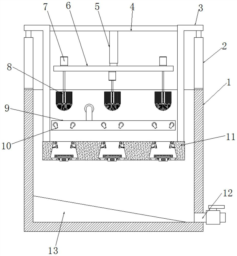
[0026] refer to Figure 1-3 , a cleaning and disinfection device for cup-like medical instruments, comprising a box body 1, a spray mechanism is fixed inside the box body 1, and electric lifting rods 2 are fixed on the outer walls on both sides of the top of the box body 1, and the extension rods of the electric lifting rod 2 The top end is fixed with a connecting rod 3, and the bottom ends of the two connecting rods 3 are fixed with the same storage board 11. The top outer wall of the storage board 11 has a plurality of storage cavities 14 equidistantly distributed, and the center of the bottom inner wall of the storage cavity 14 has a movable Mouth 27, a support mechanism is movable installed in the movable mouth 27, a clamping mechanism is fixedly installed on the top of the inner wall on both sides of the storage chamber 14, a cross bar 4 is fixed between the two connecting rods 3, and a cylinder 5 is fixed on the outer wall of the bottom of the cross bar 4 The bottom end ...

Embodiment 2

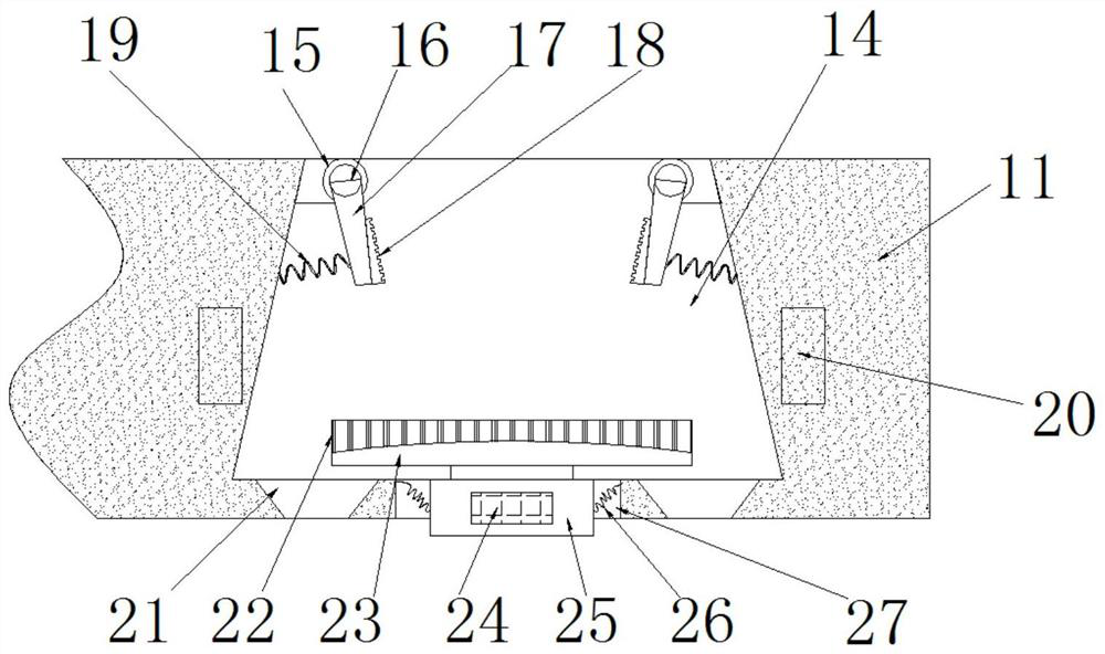
[0035] refer to Figure 4 , a cleaning and disinfection device for cup-like medical instruments, comprising a box body 1, a spray mechanism is fixed inside the box body 1, and electric lifting rods 2 are fixed on the outer walls on both sides of the top of the box body 1, and the extension rods of the electric lifting rod 2 The top end is fixed with a connecting rod 3, and the bottom ends of the two connecting rods 3 are fixed with the same storage board 11. The top outer wall of the storage board 11 has a plurality of storage cavities 14 equidistantly distributed, and the center of the bottom inner wall of the storage cavity 14 has a movable Mouth 27, a support mechanism is movable installed in the movable mouth 27, a clamping mechanism is fixedly installed on the top of the inner wall on both sides of the storage chamber 14, a cross bar 4 is fixed between the two connecting rods 3, and a cylinder 5 is fixed on the outer wall of the bottom of the cross bar 4 The bottom end of...


PUM


Abstract

The invention discloses a cleaning and disinfection device for cup medical instruments. The cleaning and disinfection device comprises a box body, wherein a spraying mechanism is fixed in the box body, and electric lifting rods are fixed to the outer walls of the two sides of the top end of the box body; connecting rods are fixed to the top ends of extension rods of the electric lifting rods, andthe same storage plate is fixed to the bottom ends of the two connecting rods; a plurality of storage cavities distributed at equal intervals are formed in the outer wall of the top of the storage plate, movable openings are formed in the central positions of the inner walls of the bottoms of the storage cavities, supporting mechanisms are movably arranged in the movable openings, and clamping mechanisms are fixedly arranged at the top ends of the inner walls of the two opposite sides of the storage cavities; and a transverse rod is fixed between the two connecting rods, an air cylinder is fixed to the outer wall of the bottom of the transverse rod, a lifting plate is fixed to the bottom end of a piston rod of the air cylinder, a plurality of motors are fixed to the outer wall of the top of the lifting plate, and cleaning mechanisms are fixed to the bottom ends of output shafts of the motors. The cleaning and disinfection device for the cup medical instruments improves the completenessof cleaning work, and avoids cleaning dead corners.

Description

technical field [0001] The invention relates to the technical field of disinfection of medical instruments, in particular to a cleaning and disinfection device for cup medical instruments. Background technique [0002] Medical devices refer to instruments, equipment, utensils, in vitro diagnostic reagents and calibrators, materials, and other similar or related items that are directly or indirectly used on the human body, including required computer software; their effects are mainly obtained through physical means, not Obtained by pharmacological, immunological or metabolic means, or with the participation of these means but only as an auxiliary function; its purpose is the diagnosis, prevention, monitoring, treatment or alleviation of disease; the diagnosis, monitoring, treatment, alleviation or function of injury Compensation; examination, replacement, regulation or support of physiological structures or processes; life support or maintenance; pregnancy control; providing...

Claims


Application Information

Patent Timeline
IPC IPC(8): B08B9/20B08B9/36B08B9/28B08B13/00F26B21/00
CPCB08B9/20B08B9/28B08B9/36B08B13/00F26B21/004
Inventor 钱椰丽
Owner 钱椰丽
Why Eureka
Try Eureka