DI channel diagnosis circuit and method

A technology for diagnosing circuits and diagnostic methods, which is applied in short-circuit testing, general control systems, electrical testing/monitoring, etc., and can solve the problems of low online dynamic detection and failure to detect faults effectively

Active Publication Date: 2020-10-23
STATE NUCLEAR POWER AUTOMATION SYST ENGCO
View PDF5 Cites 3 Cited by
  • Summary
  • Abstract
  • Description
  • Claims
  • Application Information

AI Technical Summary

Problems solved by technology

These methods cannot effectively detect faults that are not disconnected, and the degree of online dynamic detection is relatively low

Method used


Image

  • DI channel diagnosis circuit and method
  • DI channel diagnosis circuit and method
  • DI channel diagnosis circuit and method

Examples


Embodiment 1

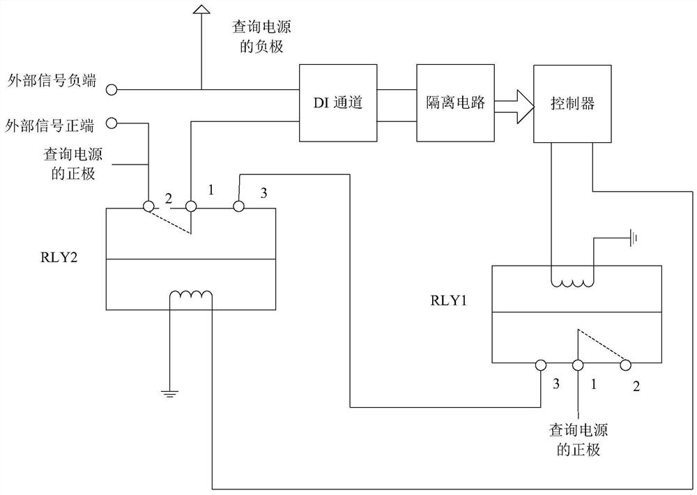
[0030] This embodiment provides a diagnostic circuit for the DI channel, such as figure 2 As shown, it includes the first relay RLY1, the second relay RLY2, the controller and the DI channel.

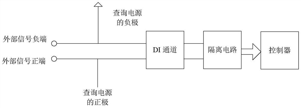
[0031] The first input end of the DI channel is connected to the negative pole of the query power supply, the second input end is connected to the common end (contact 1) of the second relay RLY2, and the output end is connected to the controller.

[0032] The normally closed contact (contact 2) of the second relay RLY2 is connected with the positive pole of the inquiry power supply; the normally open contact (contact 3) of the first relay RLY1 is connected with the normally open contact (contact 3) of the second relay RLY2 Contact 3) is connected, and the common end (contact 1) of the first relay RLY1 is connected to the positive pole of the inquiry power supply.

[0033] It should be noted that, by default, the common end of the first relay RLY1 is connected to the normally closed co...

Embodiment 2

[0047] An embodiment of the present invention provides a diagnostic method for a DI channel, which is realized by using the diagnostic circuit described in Embodiment 1. The diagnostic method includes the following steps:

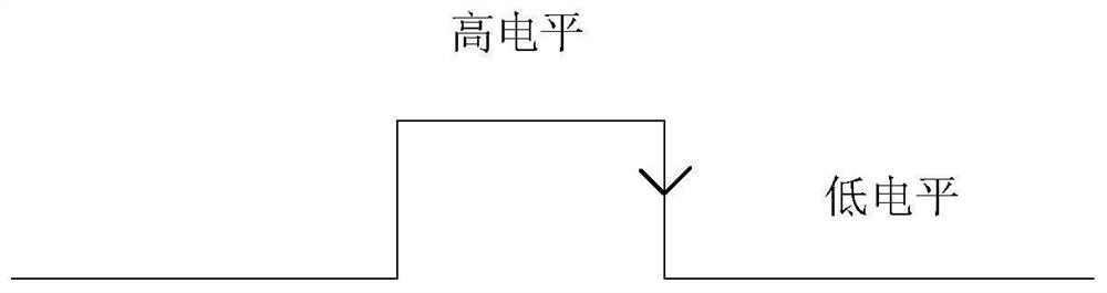
[0048] Step S201, the controller outputs a high-level signal to the coil terminal of the first relay and the coil terminal of the second relay respectively, and outputs a low-level signal to the coil terminal of the first relay after a period of delay.

[0049]In an optional implementation manner of step S201, the controller outputs high-level signals to the coil terminal of the first relay and the coil terminal of the second relay respectively at intervals.

[0050] Step S202, if the controller detects a falling edge signal, diagnose that the DI channel is normal; otherwise, diagnose that the DI channel is abnormal.

[0051] In an optional implementation manner of step S202, if the controller does not detect a falling edge signal, it outputs a fault alarm ...


PUM


Abstract

The invention discloses a DI channel diagnosis circuit and method. The DI channel diagnosis circuit comprises a first relay, a second relay, a controller and a DI channel. The first input end of the DI channel is connected to a negative electrode of a query power supply, the second input end is connected to the common end of the second relay, and the output end is connected to the controller; a normally closed contact of the second relay is connected with a positive electrode of the query power supply; the normally open contact of the first relay is connected with the normally open contact ofthe second relay, and the common end of the first relay is connected with the positive electrode of the query power supply; the controller is configured to output high-level signals to the coil ends of the first relay and the second relay and output low-level signals to the coil end of the first relay after delaying for a period of time. And if the falling edge signal is detected, the DI channel is diagnosed to be normal. By adopting a double-relay hardware structure, the automatic diagnosis function of the DI channel can be realized according to the detected falling edge signal, the cost is low, and the method is simple and effective.

Description

technical field [0001] The invention relates to the technical field of industrial control, in particular to a diagnostic circuit and method for a DI channel. Background technique [0002] DI (Digital Input, digital input) channels are widely used in the field of industrial control. Thermal power, nuclear power, coal, petroleum, chemical and other fields need to detect and analyze relative switching signals. Therefore, a large number of DI modules are required in these industrial control fields. . The DI channel of the DI module is used to collect the digital signal of the device, such as figure 1 In the example shown, the DI channel receives an external relay signal, and detects the on-off status of the external relay by detecting the on and off of the query power supply. Specifically, if the external relay is closed, the query power supply forms a loop through the DI channel, and the DI channel detects signal 1, which is a high level, and transmits it to the controller th...

Claims


Application Information

Patent Timeline
Patent Type & Authority Applications(China)
IPC IPC(8): G05B23/02G01R31/52G01R31/54
CPCG05B23/0213G01R31/52G01R31/54
Inventor 靳子洋田钢王楠马呈祥潘清王汉意李福生
Owner STATE NUCLEAR POWER AUTOMATION SYST ENGCO
Why Eureka
Try Eureka