Method for machining turbine blade expansion holes through electric spark milling

A turbine blade and milling processing technology is applied in the field of turbine engine workpiece processing, which can solve the problems of uneven shape and irregular forming position of expansion holes of turbine blades.

Active Publication Date: 2020-10-27
成都和鸿科技股份有限公司
View PDF9 Cites 4 Cited by
  • Summary
  • Abstract
  • Description
  • Claims
  • Application Information

AI Technical Summary

Problems solved by technology

[0004] Based on this, it is necessary to provide a method for EDM machining the expansion hole of the turbine blade to solve the problem of irregular position and non-uniform shape of the expansion hole of the turbine blade. By designing the hole model and writing a program, the bottom hole is cut by an EDM machine tool. The hole and the expansion hole are processed together to make the expansion hole of the turbine blade regular in position and uniform in shape to meet the theoretical design requirements

Method used


Image

  • Method for machining turbine blade expansion holes through electric spark milling
  • Method for machining turbine blade expansion holes through electric spark milling
  • Method for machining turbine blade expansion holes through electric spark milling

Examples


Embodiment Construction

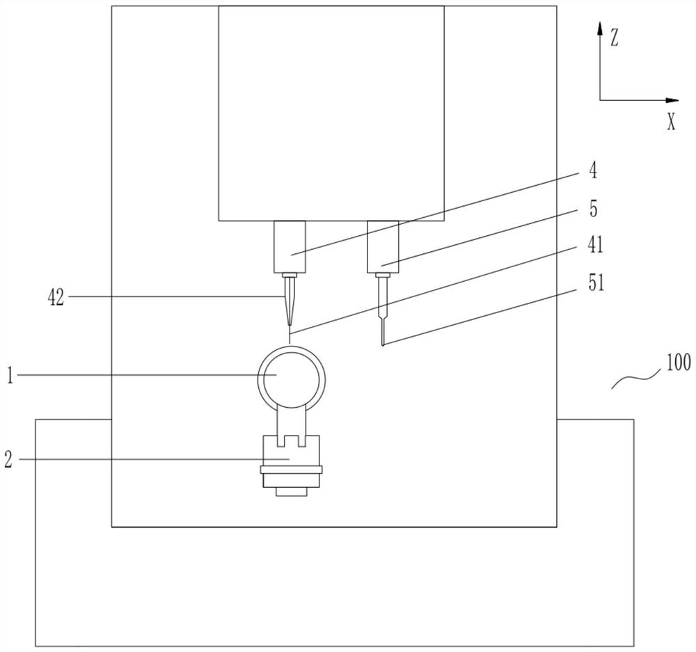
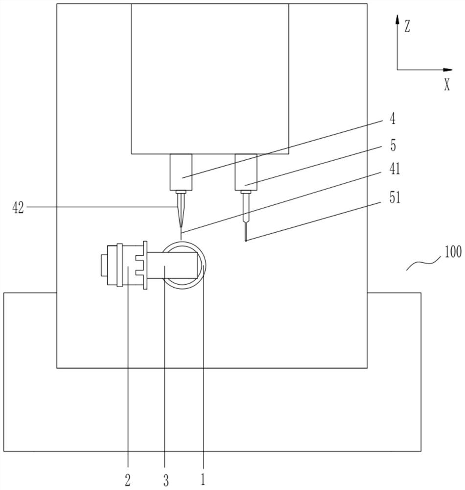
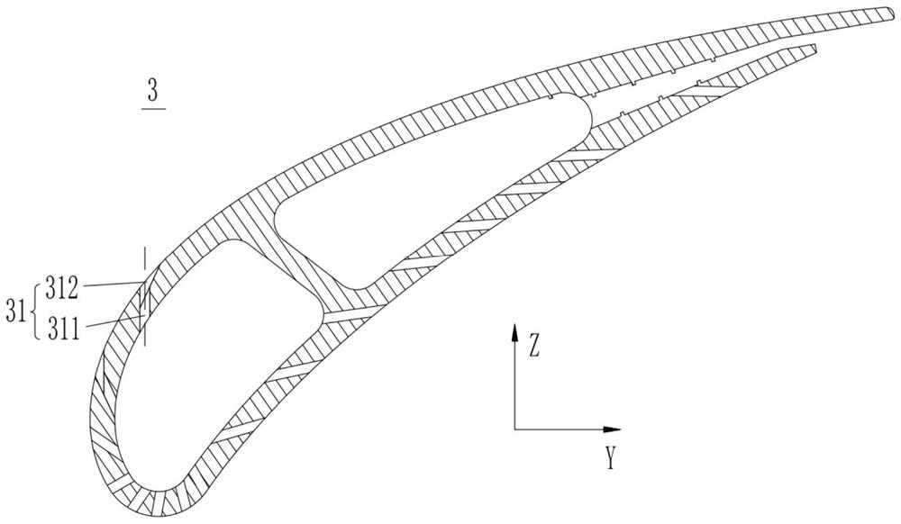
[0029] In order to facilitate the understanding of the present invention, a method of electric discharge milling for machining expansion holes of turbine blades will be described more fully below with reference to related drawings. The preferred embodiment of the method of electric discharge milling machining turbine blade expansion hole is given in the accompanying drawings. However, the method of EDM machining the expansion hole of the turbine blade can be implemented in many different forms, and is not limited to the embodiments described herein. On the contrary, the purpose of providing these embodiments is to make the disclosure of the method for electric discharge milling the expansion hole of the turbine blade more thorough and comprehensive.

[0030] In the description of this application, it should be noted that if the terms "center", "upper", "lower", "left", "right", "vertical", "horizontal", "inner", "outer" " and other indications are based on the orientation or ...


PUM


Abstract

The invention discloses a method for machining turbine blade expansion holes through electric spark milling. The method comprises the steps that a turbine blade three-dimensional model is preset; a turbine blade is installed, and the theoretical point taking orientation is measured; the corresponding preset turbine blade three-dimensional model is fitted according to the theoretical point taking orientation, hole positions, hole shapes and the number of the holes are determined, and corresponding machining electrodes are selected; the machining electrodes are subjected to loss testing and correction compensation; the machining electrodes are controlled for alignment machining to obtain single machining holes consistent with the three-dimensional model according to the three-dimensional model; and feeding and milling of the machining electrodes are repeatedly controlled till all the machining holes are machined. According to the method, the three-dimensional model is preset, then the turbine blade is subjected to configuration detection and matched with the corresponding three-dimensional model, the positions, shapes and number of the actual machining holes are determined, the corresponding machining electrodes are selected for alignment machining, and the positions, shapes and number of the machining holes are consistent with those of the three-dimensional model. The positionsare regular, the shapes are unified, and the machining technology indexes of the turbine blade expansion holes reach a high level.

Description

technical field [0001] The invention relates to the technical field of machining turbine engine workpieces, in particular to a method for electric discharge milling to process expansion holes of turbine blades. Background technique [0002] Air film cooling is a cooling technology applied to gas turbine blades. It is mainly to design a large number of air film holes on the leading edge of the turbine blade and the blade body surface. The hole diameter is generally 0.2-0.8mm, and the space angle is complicated. The high-pressure cold air is extracted from the high-pressure stage and transported to the inner channel of the blade. The cold air strengthens the convection heat transfer in the channel and takes away part of the heat. At the same time, a part of the cold air is ejected from the air film hole on the blade wall. Under the action, it bends downstream, adheres to the blade wall, forms a cold air film with a lower temperature, isolates the wall from the high-temperature...

Claims


Application Information

Patent Timeline
Patent Type & Authority Applications(China)
IPC IPC(8): B23H9/14
CPCB23H9/14
Inventor 杨超张爱民郑珂徐培江郭志强冯斌
Owner 成都和鸿科技股份有限公司
Why Eureka
Try Eureka