Double material gradient injection molding device

A gradient and mixing technology, applied in the field of double-material gradient injection molding device, can solve the problems of poor mixing effect, inconvenient use, complicated processing, etc., and achieve the effect of color transformation and roundness.

Active Publication Date: 2021-03-12
苏州宝富塑料制品有限公司
View PDF7 Cites 0 Cited by
  • Summary
  • Abstract
  • Description
  • Claims
  • Application Information

AI Technical Summary

Problems solved by technology

[0002] In the process of plastic processing, plastic granules are often used as raw materials. By melting the granule raw materials, and then injecting the granule raw materials in the molten state into the mold, the plastic is cooled and fixed. Due to the need for injection molding operations, traditional plastic processing Usually, individual colors or mixed plastic materials are used for melt injection molding, so there is usually only one single color in one injection molded product
This greatly limits the color expression of plastic products, and when plastic products require different colors, they often need to be completed by splicing different products, which not only makes the processing more complicated, but also has obvious color differences at different connection positions of injection molded parts, which affects product aesthetics
In addition, when the product is being injected, the raw materials for injection molding are mixed according to the required ratio before processing. The traditional mixing method is usually to pour the material into the mixing box and then stir it. Not only the mixing effect is poor, At the same time, due to the need to stir the raw materials as a whole, the stirring efficiency is low
Therefore, in automatic plastic granule feeding equipment, in order to ensure accurate feeding of mixed plastic granules, quantitative material chambers are usually used for feeding, and each time when different plastic granules are mixed, different feeding chambers need to be changed. Use extremely inconvenient

Method used


Image

  • Double material gradient injection molding device
  • Double material gradient injection molding device
  • Double material gradient injection molding device

Examples


Embodiment Construction

[0021] Below in conjunction with accompanying drawing and embodiment the present invention is further described:

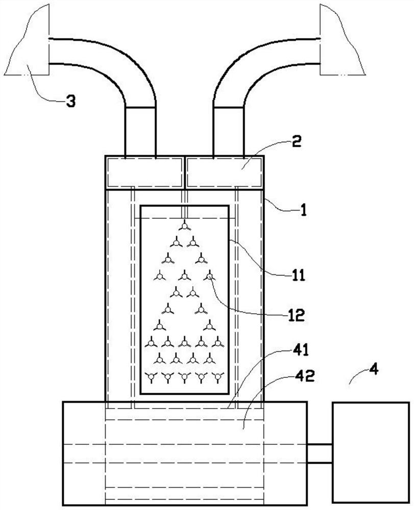
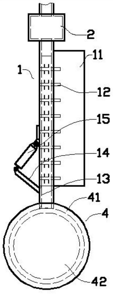
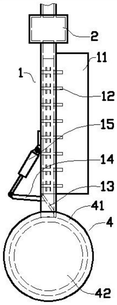
[0022] Such as figure 1 , figure 2 and image 3 As shown in the embodiment, the double-material gradual injection molding device includes a vertically placed mixed feed channel 1, and a vertical rectangular plate-shaped cavity is designed in the mixed feed channel 1, that is, the design inside the feed channel There is a flat rectangular parallelepiped column shape in the front and rear directions, and the upper part of the mixed feed channel 1 is equipped with two monochrome feed boxes 2 side by side, and the two monochrome feed boxes 2 are respectively connected with the melting pressurization module 3 are connected to each other, and the cavity part of the mixed feed channel 1 is divided into side cavities in the left and right positions and an intermediate cavity in the middle. The two monochrome feed boxes 2 are respectively designed with two A downward s...


PUM


Abstract

The invention provides a double-material gradual change type injection molding device. The device comprises a vertically-placed mixed feeding channel, wherein a vertical rectangular-plate-shaped cavity is designed in the mixed feeding channel, two single-color feeding boxes arranged side by side left and right are assembled on the upper portion of the mixed feeding channel, a power module is designed at the front part of a middle cavity of the mixed feeding channel, the power module comprises more than ten stirring shafts which horizontally and vertically go deep into a plate-shaped cavity inthe mixed feeding channel, stirring rods extend out of the stirring shafts, the stirring shafts are divided into more than three layers from top to bottom in the plate-shaped cavity of the mixed feeding channel, the stirring shafts between every two adjacent layers are arranged in a staggered manner, and a forming module is designed at the lower part of the mixed feeding channel. The device is mainly used for carrying out injection molding processing on molten substances with different colors, and can be used for integrally processing two plastic substances which have different properties andare not easy to bond.

Description

technical field [0001] The invention relates to the technical field of injection molding of granular plastics, in particular to a double-material gradual injection molding device. Background technique [0002] In the process of plastic processing, plastic granules are often used as raw materials. By melting the granule raw materials, and then injecting the granule raw materials in the molten state into the mold, the plastic is cooled and fixed. Due to the need for injection molding operations, traditional plastic processing Usually, individual colors or mixed plastic materials are used for melt injection molding, so there is usually only one single color in one injection molded product. This greatly limits the color expression of plastic products, and when plastic products require different colors, they often need to be completed by splicing different products, which not only makes the processing more complicated, but also has obvious color differences at different connectio...

Claims


Application Information

Patent Timeline
Patent Type & Authority Patents(China)
IPC IPC(8): B29C45/16B29C45/18
CPCB29C45/1634B29C45/1866
Inventor 南雅之
Owner 苏州宝富塑料制品有限公司
Why Eureka
Try Eureka