a lock

A technology of lock head and lock core, which is applied in the direction of building locks, buildings, building structures, etc. It can solve problems such as difficulty in unlocking, falling, and poor lock head anti-theft performance, and achieve good lubrication effect and prolong service life.

Active Publication Date: 2021-09-21
孙斌
View PDF8 Cites 0 Cited by
  • Summary
  • Abstract
  • Description
  • Claims
  • Application Information

AI Technical Summary

Problems solved by technology

[0002] Anti-theft doors generally use mortise door locks. The key common part of mortise door locks is the lock head. For the sake of good installation and universality of the lock, there are great defects in the anti-theft door. There are installation holes on the panel of the anti-theft door. , the mortise door lock head is installed in the installation hole, and then the lock cylinder panel is installed on the panel of the anti-theft door to cover the mortise door lock head. Since the size of the installation hole is often larger than the size of the mortise door lock head, when After the lock core panel is damaged, it is easy to pry off the lock head of the mortise door lock, thereby destroying the door lock, and other people can forcibly turn the lock head with some tools to forcibly unlock the lock, and the lock head has poor anti-theft performance;
[0003] At the same time, the lock cylinder inside the lock head must be lubricated in time after being used for a period of time, otherwise it will become difficult to unlock. The method adopted in the prior art is to inject lubricant into the lock cylinder when it is found that the lock cylinder needs to be lubricated. , this action is time-consuming and laborious at first, and it is impossible to lubricate and maintain the lock cylinder every time the lock is unlocked. The method of injecting lubricant inside is extremely inconvenient, and when the lubricant is poured in, since the lock head is placed vertically, the lubricant will fall due to gravity, and the lubrication of the lock cylinder cannot be achieved at all.

Method used


Image

  • a lock
  • a lock
  • a lock

Examples


Embodiment approach

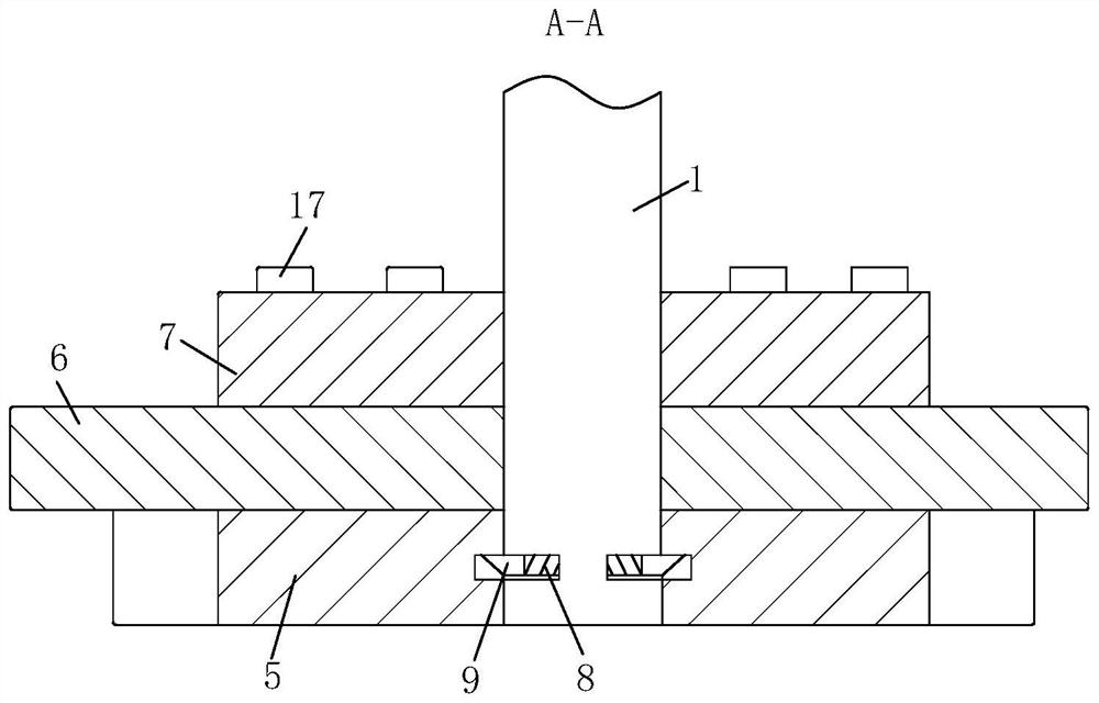
[0038] As a specific embodiment of the present invention, it also includes multiple sets of fixing screws 17, and multiple sets of fixing screws 17 screw-mount the inner fixing plate 7 and the outer door panel; by adopting the above technical scheme, the fixing screws 17 will The inner fixing plate 7 is fixedly connected with the outer door panel, which enhances the stability and safety of the lock head.

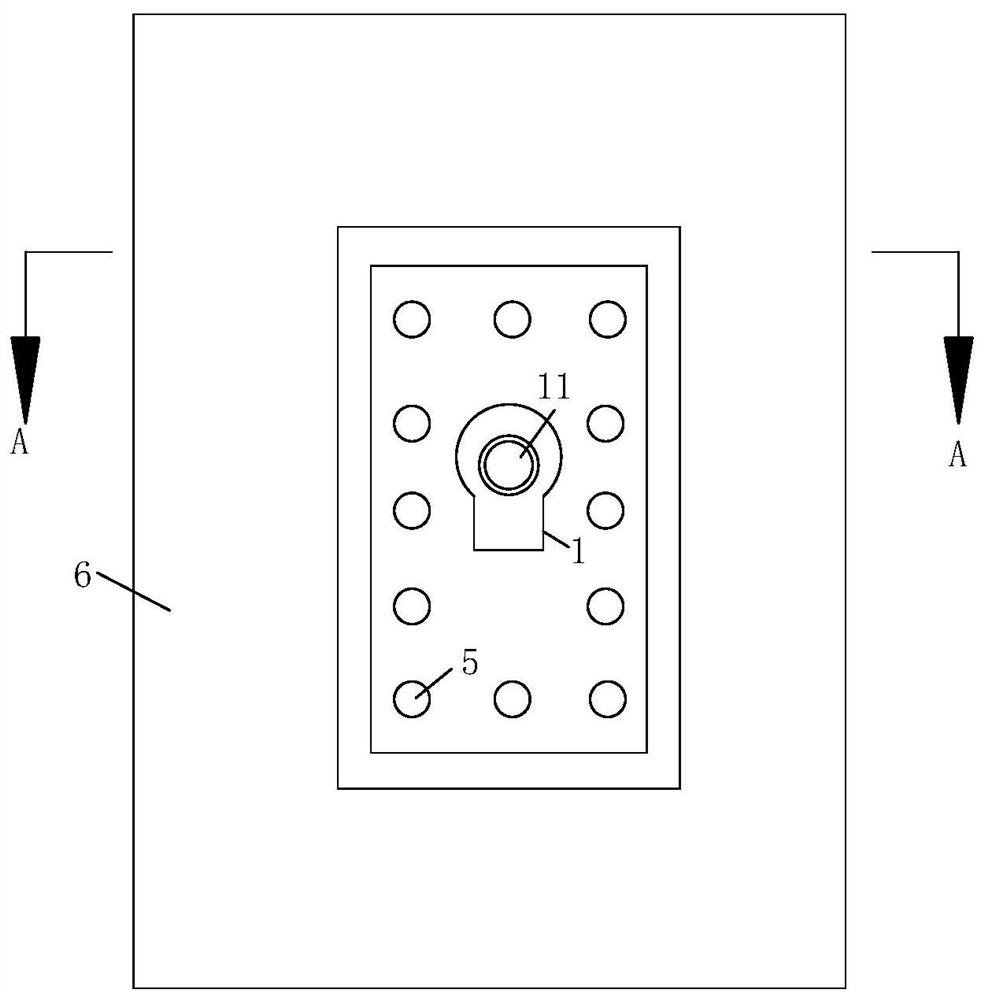
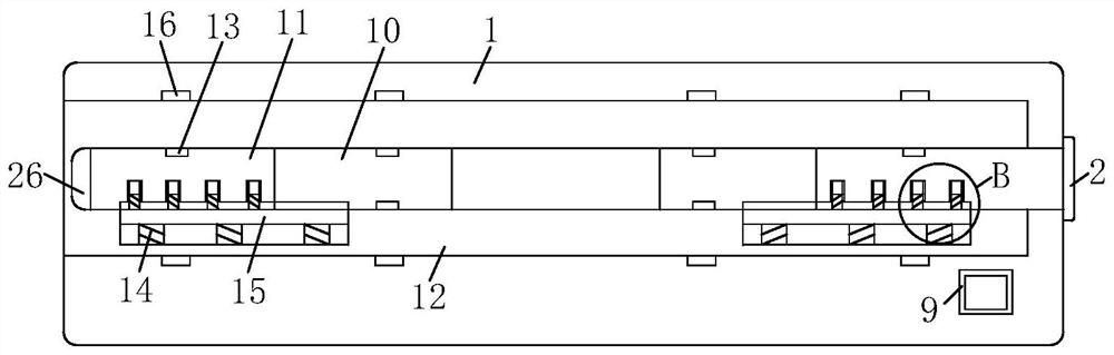
[0039] During use, the outer fixing plate 5 is riveted with the door outer plate 6, and the clamping spring 8 makes the block 9 stretch into the fixing hole. The inner fixing plate 7 connected to the front of the lock body 1 is closely attached to the door outer panel 6, and the lock head and the door panel can be fixedly installed to prevent the lock cylinder panel from being damaged. When the hole forcibly rotates the lock cylinder, because the tool cannot perfectly cooperate with the lock cylinder, the multiple groups of marbles 3 will not all shrink back to the lock hole...


PUM


Abstract

The invention discloses a lock head, which comprises a lock head body, two sets of lock cores, multiple sets of marbles, multiple sets of springs, an outer fixing plate, a door outer plate, an inner fixing plate, two sets of locking springs and two sets of clamping blocks. Both the outer fixing plate and the outer door panel are provided with lock jacks, the outer fixing plate is riveted with the outer side of the door outer panel, the front part of the lock body passes through the inner fixing plate, and the left and right ends of the front part of the lock body are both set There are clamping holes; the invention can not only lubricate the horizontally placed lock head by setting the lubrication unit, but is especially suitable for lubricating and maintaining the vertically placed lock head. For example, when the lock is installed on the ceiling or the ground, the lock cylinder is in the vertical position. Direction, when the inside of the lock cylinder needs to be lubricated, it is extremely inconvenient to pour lubricant into the inside of the lock cylinder in the prior art, but the above design solves the problem that the lock head is not easy to lubricate and maintain when the lock head is placed vertically .

Description

technical field [0001] The invention relates to the technical field of lock heads, in particular to a lock head. Background technique [0002] Anti-theft doors generally use mortise door locks. The key common part of mortise door locks is the lock head. For the sake of good installation and universality of the lock, there are great defects in the anti-theft door. There are installation holes on the panel of the anti-theft door. , the mortise door lock head is installed in the installation hole, and then the lock cylinder panel is installed on the panel of the anti-theft door to cover the mortise door lock head. Since the size of the installation hole is often larger than the size of the mortise door lock head, when After the lock core panel is damaged, it is easy to pry off the lock head of the mortise door lock, thereby destroying the door lock, and other people can forcibly turn the lock head with some tools to forcibly unlock the lock, and the lock head has poor anti-thef...

Claims


Application Information

Patent Timeline
Patent Type & Authority Patents(China)
IPC IPC(8): E05B17/08E05B15/00
CPCE05B15/00E05B17/08
Inventor 斯燕方殷玲
Owner 孙斌
Why Eureka
Try Eureka