
3D imaging film

An imaging and thin-film technology that can be used in instruments and other directions to solve problems such as inability to interpret moiré images and moiré image distortion

Active Publication Date: 2020-10-27
SHINE OPTOELECTRONICS KUNSHAN CO LTD
View PDF11 Cites 1 Cited by
  • Summary
  • Abstract
  • Description
  • Claims
  • Application Information

AI Technical Summary

Problems solved by technology

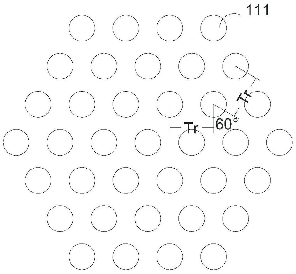
However, Moiré magnification is not a traditional lens magnification. If the microlens period Tr of the lens layer or the micropattern period Tb of the pattern layer are set differently, the displayed Moiré image will be distorted.
Therefore, the above-mentioned periodic theory cannot explain the variable-period Moiré image

Method used


Image

  • 3D imaging film
  • 3D imaging film
  • 3D imaging film

Examples


Embodiment Construction

[0048] In order to facilitate the understanding of the present invention, the present invention will be described more fully below with reference to the associated drawings. Preferred embodiments of the invention are shown in the accompanying drawings. However, the present invention can be implemented in many different forms and is not limited to the embodiments described below. On the contrary, the purpose of providing these embodiments is to make the disclosure of the present invention more thorough and comprehensive.

[0049] Unless otherwise defined, all technical and scientific terms used herein have the same meaning as commonly understood by one of ordinary skill in the technical field of the invention. The terminology used herein in the description of the present invention is only for the purpose of describing specific embodiments, and is not intended to limit the present invention. As used herein, the term "and / or" includes any and all combinations of one or more of ...


PUM


Abstract

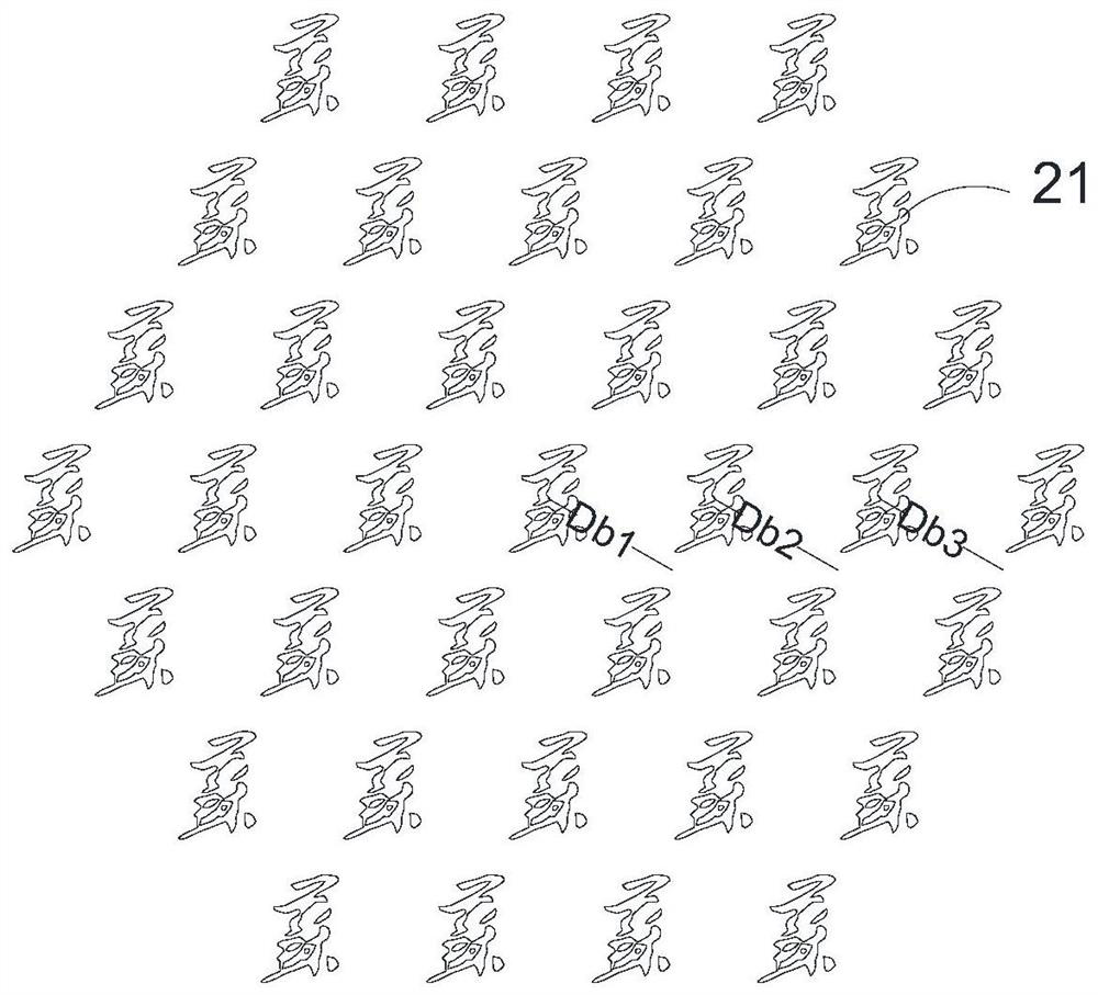
The invention discloses a 3D imaging film. The 3D imaging film comprises a microstructure layer and a pattern layer. The microstructure layer comprises at least one focusing unit, each focusing unit comprises a plurality of distributed microstructures, and the distance between every two adjacent microstructures is defined as Dr. The pattern layer comprises at least one image-text unit, each image-text unit comprises a plurality of micro image-texts which are distributed, and the distance between every two adjacent micro image-texts is defined as Db. The Dr and / or the Db can change, the focusing unit is matched with the image-text unit, and the microstructures carry out sampling from the micro image-texts to form images with variations. The arrangement of the microstructures and / or the micro image-texts can change, and the positions of the microstructures and the micro image-texts can be accurately reflected through the Dr and the Db, so that a preset image can be formed, and the imageis not distorted.

Description

technical field [0001] The invention relates to the technical field of optical films, in particular to a 3D imaging film. Background technique [0002] Various 3D imaging technologies have received more and more attention in the fields of information, display, medical treatment, military affairs, anti-counterfeiting, and decoration. The use of microlens technology to achieve three-dimensional imaging has great potential and prospects. With the development of microlens array manufacturing process and the popularization of high-resolution printing and image sensors, 3D imaging technology has attracted more and more attention, and various performances of 3D imaging, such as depth of field, viewing angle, etc., have also been greatly improved. improvement. [0003] The common 3D imaging technology is periodical moiré imaging, and its design principle is: the microlenses of the lens layer are set periodically, and its period is Tr; the micropatterns of the pattern layer are als...

Claims


Application Information

Patent Timeline
Patent Type & Authority Applications(China)
IPC IPC(8): G02B30/27
Inventor 郑伟伟张海英申溯
Owner SHINE OPTOELECTRONICS KUNSHAN CO LTD
Learn More