Medical image processing apparatus and method

a technology of medical image and processing apparatus, applied in image rendering, tomography, instruments, etc., can solve the problems of difficult to precisely grasp the position and size of a polyp in the tube wall, the diameter of the tubular tissue is not always constant, and the obstruction of image diagnosis

Inactive Publication Date: 2010-06-10
ZIOSOFT
View PDF6 Cites 20 Cited by
  • Summary
  • Abstract
  • Description
  • Claims
  • Application Information

AI Technical Summary

Benefits of technology

[0024]It is an illustrative aspect of the present invention to provide a medical image processing apparatus and a method capable of generating a cylindrical projection image of a tubular tissue with no distortion in the aspect ratio even if the diameter of the tubular tissue is changed.

Problems solved by technology

However, to observe the tubular tissue while moving in the inside of the tubular tissue, it is hard to precisely grasp the position and the size of a polyp in the tube wall.
This is because the diameter of the tubular tissue is not always constant.
Consequently, for example, it becomes hard to distinguish between the polyp and the tissue of the wall of the colon, which leads to obstruction of image diagnosis.

Method used


Image

  • Medical image processing apparatus and method
  • Medical image processing apparatus and method
  • Medical image processing apparatus and method

Examples


Embodiment Construction

[0041]Exemplary embodiments of the present invention will be now described with reference to the drawings.

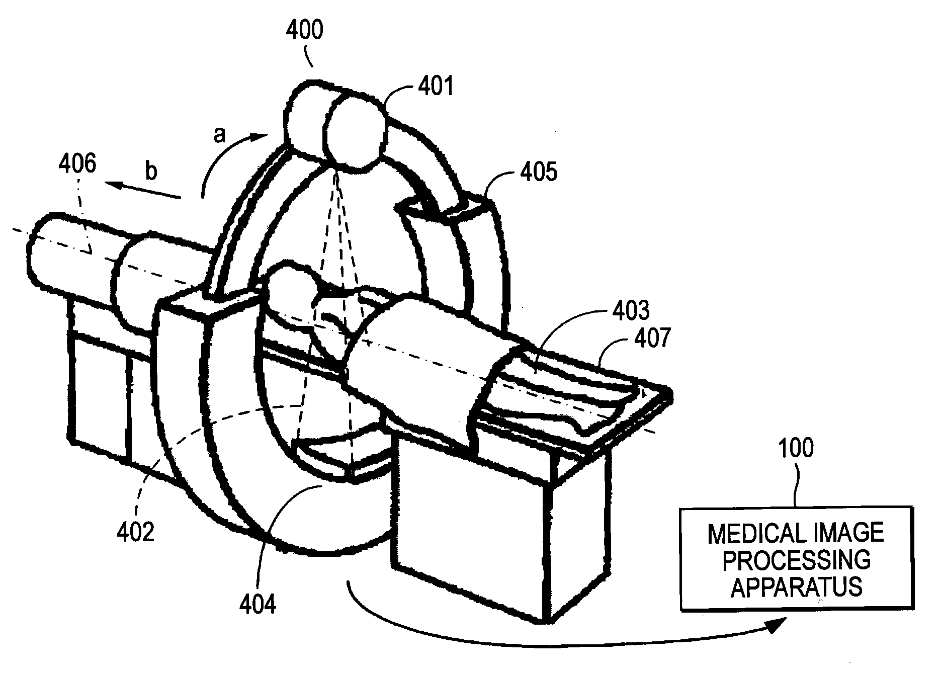
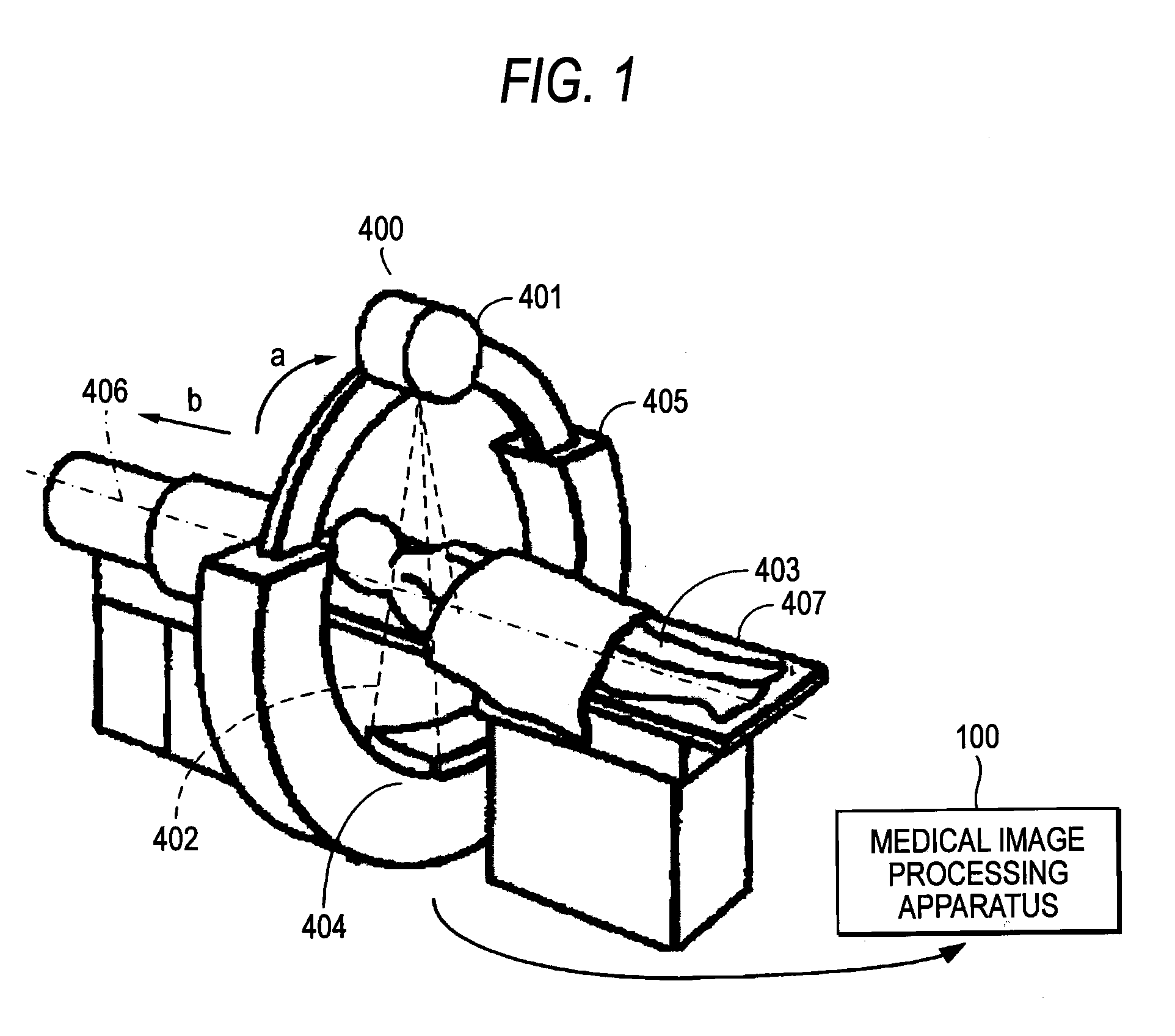
[0042]FIG. 1 shows an example of using a medical image processing apparatus 100 according to an exemplary embodiment of the present invention in combination with a computed tomography (CT) apparatus 400. As shown in FIG. 1, the CT apparatus 400 is used to visualize the tissue of a specimen. The CT apparatus 400 includes an X-ray source 401 that is a radiation source of an X-ray beam bundle 402, an X-ray detector 404, a ring-like gantry 405, and a table 407 through which an X ray passes.

[0043]The X-ray source 401 radiates the X-ray beam bundle 402, which is shaped like a pyramid as indicated by the chain line in the figure. The X-ray detector 404 detects the X-ray beam bundle 402 passing through a patient 403 on the table 407. Further, the X-ray detector 404 outputs a signal of the detected X-ray beam bundle 402 to an medical image processing apparatus 100. The X-ray source 401 a...


PUM


Abstract

There is provided a medical image processing apparatus for visualizing a tubular tissue contained in volume data. The apparatus includes: a central path determination section that determines a central path of the tubular tissue; a diameter determination section that determines a diameter of the tubular tissue at a certain point on the central path; a spacing determination section that determines at least two or more different projection spacings for projecting virtual rays along the central path, depending on the diameter of the tubular tissue; a cylindrical projection section that projects the virtual rays along the central path with the projection spacing that depends on the diameter of the tubular tissue; and an image generation section that generates a cylindrical projection image of the tubular tissue, based on information provided by projecting the virtual rays and the volume data.

Description

[0001]This application is based on and claims priority from Japanese Patent Application No. 2008-311192, filed on Dec. 5, 2008, the entire contents of which are hereby incorporated by reference.BACKGROUND OF THE INVENTION[0002]1. Technical Field[0003]The present disclosure relates to a medical image processing apparatus and method. More particularly, the present disclosure relates to a medical image processing apparatus and method for generating a cylindrical projection image of a tubular tissue with no distortion in the aspect ratio.[0004]2. Related Art[0005]In recent years, attention has been focused on a technology of visualizing the inside of a three-dimensional object according to the image processing technology using a computer. Particularly, medical diagnosis using an image of Computed Tomography (CT) or a Magnetic Resonance Imaging (MRI), which makes it possible to visualize the inside of a living body, has been widely conducted in a medical field to find a lesion at an earl...

Claims


Application Information

Patent Timeline
Patent Type & Authority Applications(United States)
IPC IPC(8): G06K9/00A61B6/03G06T15/08G06T19/00
CPCG06T11/008G06T19/00G06T15/20G06T15/08G06T15/10G06T2215/08
Inventor MATSUMOTO, KAZUHIKO
Owner ZIOSOFT
Why Eureka
Try Eureka