Vibration prevention device for new energy battery assembly

A battery assembly and new energy technology, applied in battery pack components, electrical components, circuits, etc., can solve the problems of limited shock absorption, no shock absorption, and lack of shock absorption functions.

Inactive Publication Date: 2020-10-27
陈圣利
View PDF0 Cites 0 Cited by
  • Summary
  • Abstract
  • Description
  • Claims
  • Application Information

AI Technical Summary

Problems solved by technology

[0002] New energy batteries are gradually applied to automobiles, which have the advantages of strong environmental protection and good energy-saving effects. Such batteries and their components used in new energy vehicles will affect the safety of batteries due to different road conditions or the impact of emergencies. For example, when the car has an instantaneous inertial force or a collision impact, the battery fixing device lacks an effective shock-proof and shock-absorbing function, and the battery will follow the vibration, which will lead to battery damage, and in severe cases, an explosion will occur...

Method used


Image

  • Vibration prevention device for new energy battery assembly
  • Vibration prevention device for new energy battery assembly
  • Vibration prevention device for new energy battery assembly

Examples


Embodiment 1

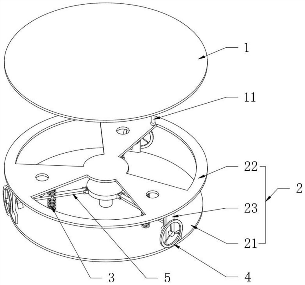
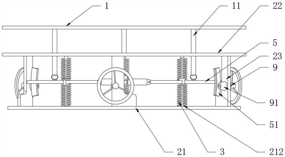
[0032] see Figure 1-3 , a shock-absorbing device for new energy battery components, including a battery mounting plate 1, a supporting device 2, a spring 3, a flywheel disc 4 and a connecting rod 5, the battery mounting plate 1 is used for fixing and installing the battery and its components, and the supporting device 2 It is used to be installed on the automobile and plays the role of support and positioning; the support device 2 is provided with a lower circular plate 21 and an upper circular plate 22 located on the upper part of the lower circular plate 21 and distributed through the axis center, and the lower surface wall of the upper circular plate 22 And near the outer periphery, three support plates 23 evenly distributed in the circumferential direction are fixedly connected with the lower circular plate 21. One side of the flywheel disc 4 is fixedly provided with a connecting shaft 9 at the center of the disc, and one end of the connecting shaft 9 runs through the supp...

Embodiment 2

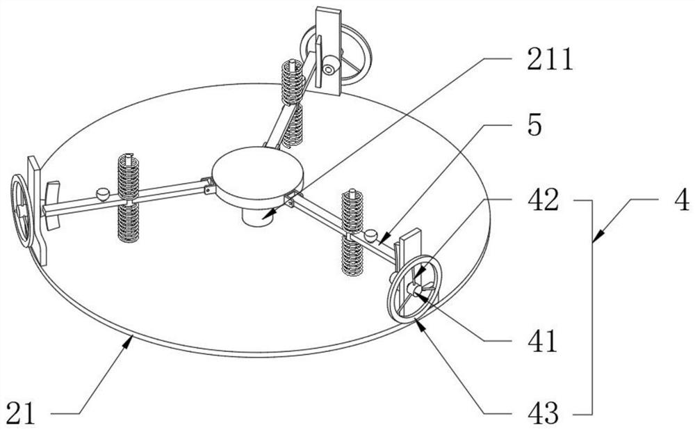
[0034] see image 3 with Figure 4, and the difference from Embodiment 1 is that the flywheel disc 4 is provided with an inner shaft 41, a fixed shaft 42 and an annular plate 43 sequentially along the radial direction from inside to outside, and the outer wall of the inner shaft 41 passes through the inner surface of the fixed shaft 42 and the annular plate 43 The wall is fixedly connected, and one side of the annular plate 43 is detachably connected with an annular counterweight plate 6. Specifically, one side of the annular plate 43 and one side of both sides of the annular counterweight plate 6 are fixedly provided with permanent magnet rings 102. When increasing the buffer strength, the inertial resistance of the flywheel disc 4 rotation can be improved by increasing the ring-shaped counterweight plate 6. If the rotational inertial resistance of the flywheel disc 4 is small, the battery mounting plate 1 is prone to tilt for smaller vibrations, and it is also There will be...

Embodiment 3

[0036] see Figure 4 The difference from Embodiment 2 is that the number of fixed shafts 42 is three and is evenly distributed in the circumferential direction, the axis of the fixed shaft 42 is perpendicular to the axis of the connecting shaft 9, and the fixed shaft 42 is sleeved with a weight sleeve 7 and a spring 2. 8. The counterweight sleeve 7 is located on one side of the inner shaft 41. When the flywheel disc 4 accelerates and rotates to a certain speed, the counterweight sleeve 7 slides radially outward by the centrifugal force generated by its own weight and compresses the spring 2. 8, the counterweight The radius of gyration of the cover 7 increases, thereby dynamically increasing the rotational inertial resistance of the flywheel disc 4, thereby impelling the flywheel disc 4 to rotate and decelerate in one direction. When the external shock source disappears, the flywheel disc 4 can be accelerated to a static state. Furthermore, the battery mounting plate 1 is stabi...


PUM


Abstract

The invention discloses a vibration prevention device for a new energy battery assembly. The vibration prevention device comprises a battery mounting plate, a supporting device, a first spring, a flywheel disc and a connecting rod. In the present invention, three connecting rods are arranged, included angles between the adjacent connecting rods are the same; the adjacent three connecting rods arehinged with a supporting shaft arranged on the lower circular plate; the three connecting rods can swing up and down; the other ends are meshed with the flywheel disc rotationally connected to the upper circular plate through a supporting plate; the connecting rod swings up and down to drive the flywheel disc to rotate positively and negatively; the three connecting rods are elastically connectedbetween the lower circular plate and the upper circular plate positioned at the upper part of the lower circular plate; the three connecting rods are all in spherical hinge connection with the batterymounting plate used for mounting a battery, so that when the lower circular plate vibrates, the battery vibrates along with the lower circular plate, but the vibration direction of the battery is oneunder the action of the flywheel disc and gradually tends to be static, the situation that the battery vibrates along with the lower circular plate is avoided, and the vibration prevention effects are achieved.

Description

technical field [0001] The invention relates to the technical field of new energy batteries, in particular to a shockproof and shock absorbing device for new energy battery components. Background technique [0002] New energy batteries are gradually applied to automobiles, which have the advantages of strong environmental protection and good energy-saving effects. Such batteries and their components used in new energy vehicles will affect the safety of batteries due to different road conditions or the impact of emergencies. For example, when the car has an instantaneous inertial force or a collision impact, the battery fixing device lacks an effective shock-proof and shock-absorbing function, and the battery will follow the vibration, which will lead to battery damage, and in severe cases, it will explode; [0003] At present, there are shock absorbing devices on the market for the installation and positioning of such batteries, usually using springs or hydraulic shock absor...

Claims


Application Information

Patent Timeline
IPC IPC(8): H01M2/10
CPCY02E60/10
Inventor 陈圣利
Owner 陈圣利
Why Eureka
Try Eureka