
Camera module, control method and device thereof and electronic equipment

A technology for camera modules and electronic equipment, which can be applied to sub-office equipment, televisions, electrical components, etc., and can solve problems that affect the strength of circuit boards and increase costs

Pending Publication Date: 2020-10-27
BEIJING XIAOMI MOBILE SOFTWARE CO LTD
View PDF0 Cites 10 Cited by
  • Summary
  • Abstract
  • Description
  • Claims
  • Application Information

AI Technical Summary

Problems solved by technology

However, reducing the camera aperture will affect the imaging effect of the camera module, and the way of digging holes in the circuit board will affect the strength of the circuit board and increase the cost

Method used


Image

  • Camera module, control method and device thereof and electronic equipment
  • Camera module, control method and device thereof and electronic equipment
  • Camera module, control method and device thereof and electronic equipment

Examples


Embodiment Construction

[0051] Reference will now be made in detail to the exemplary embodiments, examples of which are illustrated in the accompanying drawings. When the following description refers to the accompanying drawings, the same numerals in different drawings refer to the same or similar elements unless otherwise indicated. The implementations described in the following exemplary examples do not represent all implementations consistent with the present disclosure. Rather, they are merely examples of apparatuses and methods consistent with aspects of the present disclosure as recited in the appended claims.

[0052] The terminology used in the present disclosure is for the purpose of describing particular embodiments only, and is not intended to limit the present disclosure. As used in this disclosure and the appended claims, the singular forms "a", "the", and "the" are intended to include the plural forms as well, unless the context clearly dictates otherwise. It should also be understood...


PUM


Abstract

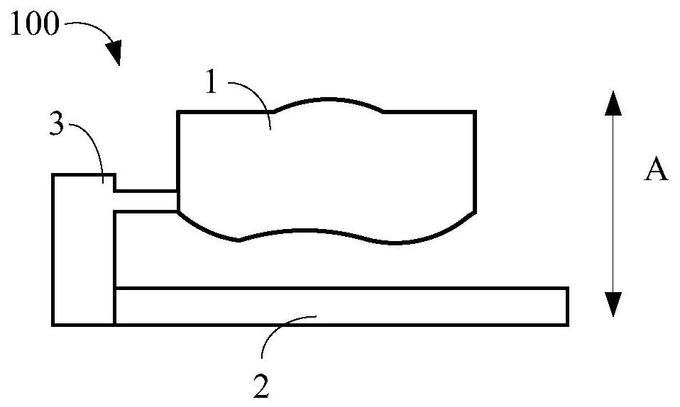
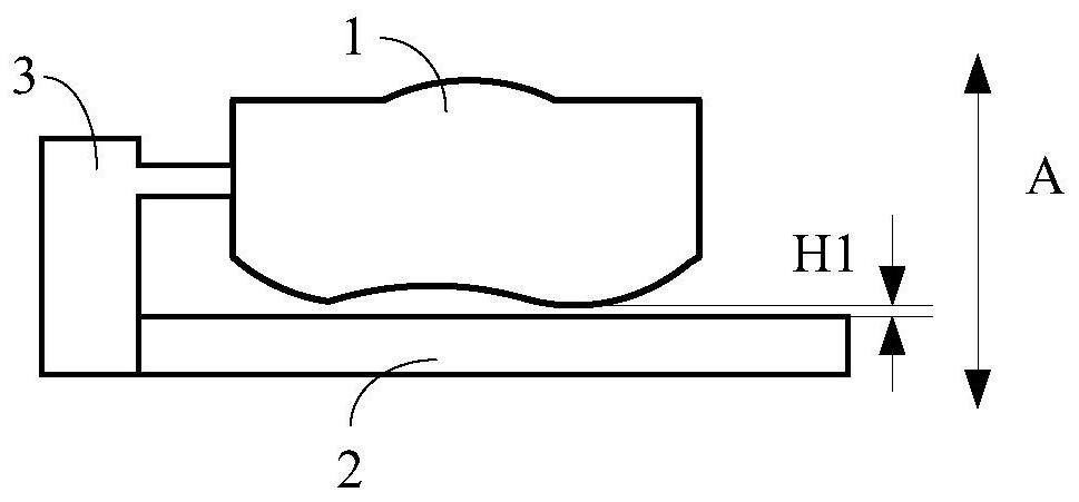
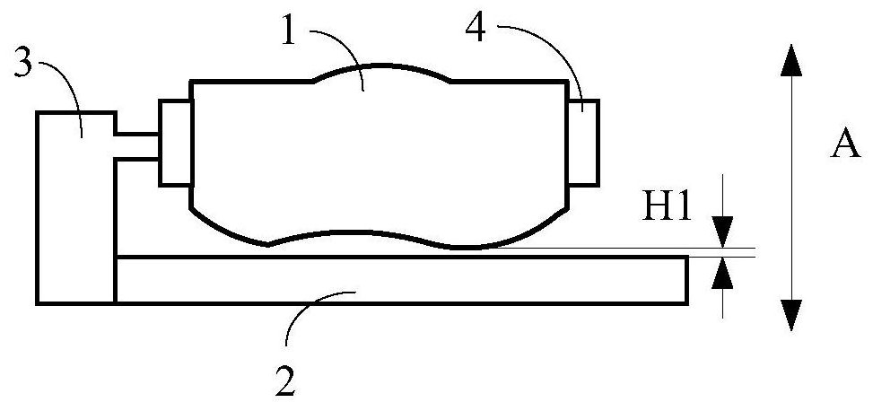
The invention relates to a camera module, a control method and device thereof and electronic equipment. The camera module comprises a lens; a photosensitive device, wherein the photosensitive device and the lens are arranged along the thickness direction of the camera module; and a first drive mechanism matched with the lens, so that, the first driving mechanism drives the lens to be far away from the photosensitive device along the thickness direction of the camera module when the camera module is switched to a photographing state, and drives the lens to be close to the photosensitive devicealong the thickness direction of the camera module when the camera module is switched to a non-photographing state.

Description

technical field [0001] The present disclosure relates to the technical field of terminals, and in particular, to a camera module, its control method and device, and electronic equipment. Background technique [0002] At present, with the rapid development of various technologies in the terminal field, users have gradually increased requirements for various functions and aesthetics of electronic devices. For example, the user hopes to improve the photographing effect of the electronic device, so as to increase the similarity between the photographed image and the real scene as much as possible. Therefore, in order to meet the needs of users, designers usually configure larger-sized camera chips for electronic devices, so as to improve the photographing effect and improve the photographing performance. [0003] In related technologies, in order to configure a large-sized camera chip in an electronic device, the height of the camera module can be reduced by reducing the apertu...

Claims


Application Information

Patent Timeline
Patent Type & Authority Applications(China)
IPC IPC(8): H04M1/02H04N5/225H04N5/232
CPCH04M1/0264H04N23/57H04N23/55H04N23/51H04N23/67H04N23/667
Inventor 尹志东
Owner BEIJING XIAOMI MOBILE SOFTWARE CO LTD
Learn More