Clamping and limiting device for PCB

A technology of a PCB board and a limiting device is applied in the field of clamping and limiting devices of the PCB board, and can solve the problems of affecting the processing accuracy, the shaking of the PCB board, and the processing error.

Active Publication Date: 2020-10-27
台州市路桥聚鑫电子有限公司
View PDF9 Cites 2 Cited by
  • Summary
  • Abstract
  • Description
  • Claims
  • Application Information

AI Technical Summary

Problems solved by technology

[0002] In the process of PCB board processing, the PCB board needs to be placed on the working platform of the CNC machine tool, and the PCB board is fixed on the working platform by negative pressure adsorption. However, the PCB board will shake slightly during the processing process. This will lead to processing errors. Therefore, in the prior art, two sets of opposite pneumatic splint structures are set, and the splints are used to clamp and limit the opposite sides of the PCB board to prevent shaking. However, in this case, the splints only limit the PCB. The side of the board, during the processing process, the PCB board will still have a slight vertical square displacement, which will affect the processing accuracy

Method used


Image

  • Clamping and limiting device for PCB
  • Clamping and limiting device for PCB
  • Clamping and limiting device for PCB

Examples


Embodiment Construction

[0022] The specific implementation manners of the present invention will be further described in detail below in conjunction with the accompanying drawings and embodiments. The following examples are used to illustrate the present invention, but are not intended to limit the scope of the present invention.

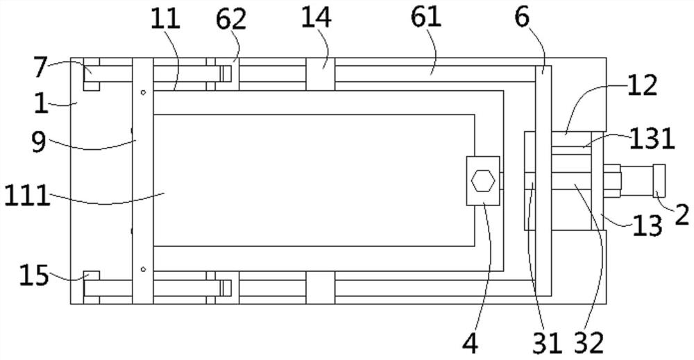
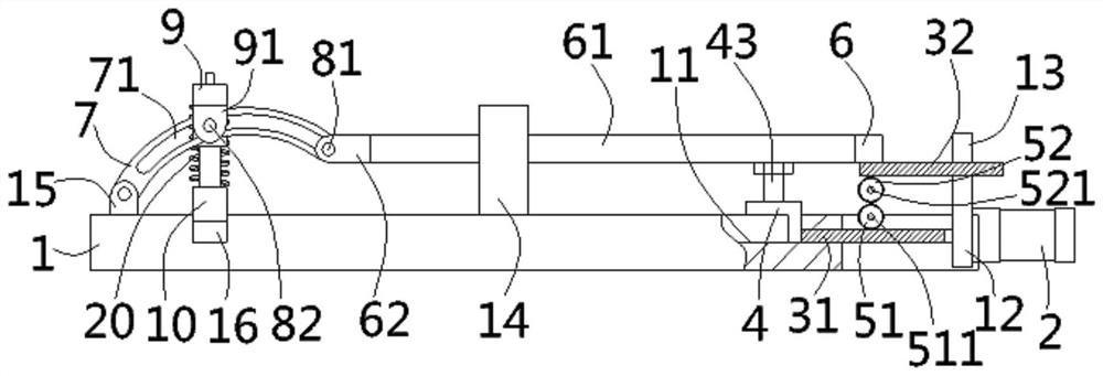
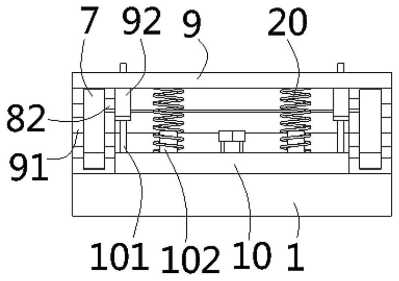
[0023] The following content reference Figure 1 to Figure 4 .

[0024] A clamping and limiting device for a PCB board according to the present invention includes a clamping platform 1, a rectangular concave platform 11 is formed on the upper end surface of the clamping platform, and a through clip is formed on the bottom surface of the concave platform. The rectangular slot 111 on the lower end surface of the mounting platform, the length and width of the concave platform are respectively greater than the length and width of the rectangular slot, the middle part of the right side of the clamping platform is formed with a notch 12, and the right side of the notch is fixed...


PUM


Abstract

The invention discloses a clamping and limiting device for a PCB, which comprises a clamping platform, wherein a concave table is formed on the clamping platform, a notch is formed in the clamping platform, a supporting plate is fixed to the notch, a pushing air cylinder is fixed to the supporting plate, a lower rack plate is fixed to the pushing air cylinder, a pushing block is fixed to the lowerrack plate, the lower rack plate is meshed with a lower gear, the lower gear is meshed with an upper gear, the upper gear is meshed with an upper rack plate, a linkage rod is fixed to the upper rackplate, and a pull rod is fixed to the linkage rod; a connector is fixed on the pull rod, a driving rod is inserted into the connector, an arc-shaped guide groove is formed in the driving rod, a connecting shaft is inserted into the guide groove, the two ends of the connecting shaft are inserted into the connector, a pressing rod is arranged on the upper side of the driving rod, a pin shaft is inserted into the guide groove and fixed to the pressing rod, a pressing strip is arranged on the lower side of the driving rod, a connecting column is formed on the upper end face of the strip, and a pressure spring is fixedly inserted into the connecting column in a sleeved mode and fixed to the pressing rod.

Description

technical field [0001] The invention relates to the technical field of PCB board processing equipment, in particular to a clamping and limiting device for PCB boards. Background technique [0002] In the process of PCB board processing, the PCB board needs to be placed on the working platform of the CNC machine tool, and the PCB board is fixed on the working platform by negative pressure adsorption. However, the PCB board will shake slightly during the processing process. This will lead to processing errors. Therefore, in the prior art, two sets of opposite pneumatic splint structures are set, and the splints are used to clamp and limit the opposite sides of the PCB board to prevent shaking. However, in this case, the splints only limit the PCB. The side of the board, during the processing process, the PCB board will still have a slight vertical square displacement, which will affect the processing accuracy. [0003] In view of the above-mentioned defects, the designer acti...

Claims


Application Information

Patent Timeline
Patent Type & Authority Applications(China)
IPC IPC(8): H05K3/00
CPCH05K3/00H05K2203/1509
Inventor 冯超
Owner 台州市路桥聚鑫电子有限公司
Why Eureka
Try Eureka