An automatic hemostasis presser
A technology of tourniquet and pressing part, which is applied in the field of automatic hemostatic press, can solve problems such as difficulties, and achieve the effect of reducing operation actions, realizing miniaturization, and realizing automatic supply
- Summary
- Abstract
- Description
- Claims
- Application Information
AI Technical Summary
Problems solved by technology
Method used
Image
Examples
Embodiment 1
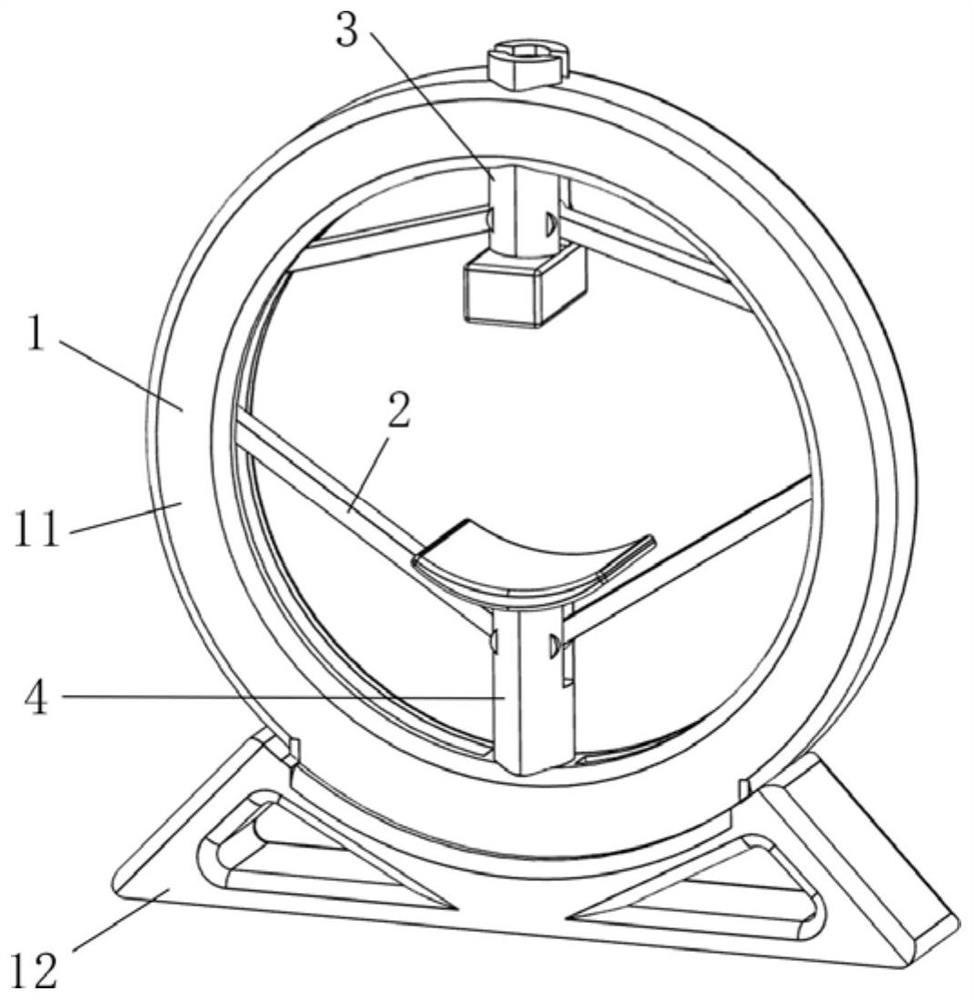
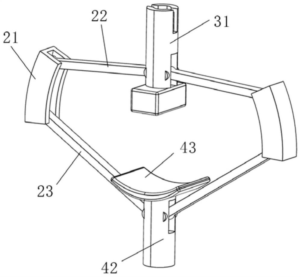
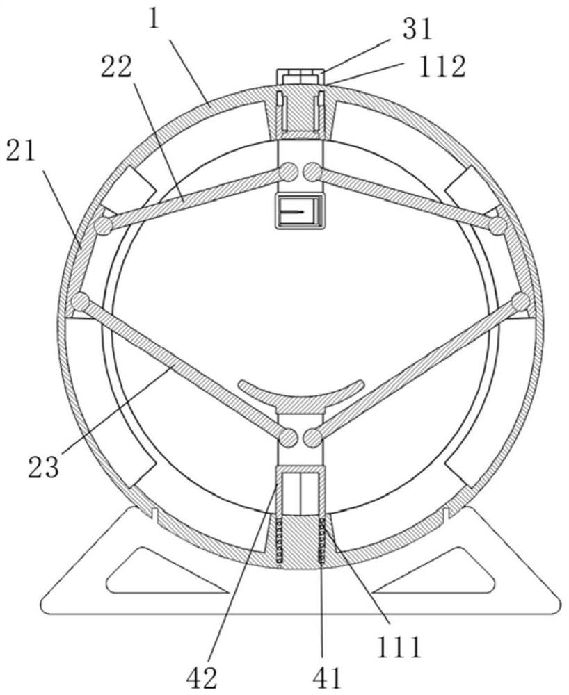
[0029] Such as Figure 1~3 As shown, this embodiment provides an automatic hemostasis presser, which includes a bracket module 1 , a transmission module 2 , an arm pressing module 3 and an arm support module 4 .
[0030] The support module 1 comprises a base 12 and an annular track frame 11, the annular track frame 11 is vertically arranged on the base 12, and the inside of the annular track frame 11 is a cavity to form a track; the base 12 adopts a hollow triangular shape, and the interior is divided into two In part, while reducing material costs, the load-bearing structure is optimized, and the integrity of the device is also improved, making it more beautiful.
[0031] The arm pressing module 3 and the arm supporting module 4 are respectively arranged on the top and the bottom of the ring-shaped track frame 11 , and both can be stretched up and down in the ring-shaped track frame 11 . Specifically, the arm support module 4 includes an arm support plate 43 , a return sprin...
Embodiment 2
[0035]The basic structure of this embodiment is the same as that of Embodiment 1, the difference is that: the arm pressing module 3 includes a pressing mechanism 32, which is installed on the bottom of the arm pressing module 3, as Figure 5 and Figure 6 shown. The pressing mechanism 32 includes a pressing push rod 321 , a first motor 322 and an ultrasonic sensor. The first motor 322 drives the pressing push rod 321 to move up and down through the gear structure, and the bottom end of the pressing push rod 321 is a suction cup 321a, which adopts an existing vacuum suction cup. The ultrasonic sensor is installed on the limit of pressing push rod 321 and is used for detecting whether the lower arm is within the set distance.
[0036] The working process and principle of this embodiment are as follows: when in use, first suck a hemostatic patch under the suction cup 321a. After the arm pressing module 3 descends, the ultrasonic sensor responds and starts monitoring. When the...
Embodiment 3
[0038] This embodiment is an improved version of Embodiment 2, and the arm pressing module 3 also includes a tourniquet replacement unit 33, such as Figure 7 shown. The tourniquet replacement unit 33 includes a pulley 332 and a second motor 331 . The second motor 331 is connected to the rotating shaft of the pulley 332. The tourniquet 5 is wound on the pulley 332. The tourniquet replacement unit 33 is provided with an outlet slot 333 facing the push rod 321, so that one end of the tourniquet 5 passes through the outlet slot. 333. The tourniquet 5 is formed by connecting hemostatic sheets with a protective film, and the adjacent hemostatic sheets are electrically connected. A knife edge can also be set at the bottom of the outlet groove 333 . After one pressing operation is finished, the second motor 331 can drive the pulley 332 to make the tourniquet 5 protrude from the outlet slot 333 . Press the suction cup 321a of the push rod 321 to start sucking the tourniquet 5, and...
PUM
 Abstract
Description
Claims
Application Information
 - R&D
- Intellectual Property
- Life Sciences
- Materials
- Tech Scout
- Unparalleled Data Quality
- Higher Quality Content
- 60% Fewer Hallucinations
Browse by: Latest US Patents, China's latest patents, Technical Efficacy Thesaurus, Application Domain, Technology Topic, Popular Technical Reports.
© 2025 PatSnap. All rights reserved.Legal|Privacy policy|Modern Slavery Act Transparency Statement|Sitemap|About US| Contact US: help@patsnap.com


