Bending device for aluminum alloy ingot machining and forming

A processing forming and bending device technology, which is applied in the field of aluminum alloy ingot processing, can solve the problems of manual pressing and low bending efficiency, and achieve the effects of avoiding offset, improving bending efficiency, and improving bending quality

Pending Publication Date: 2022-03-08
江苏绿创新材料科技有限公司
View PDF0 Cites 0 Cited by
  • Summary
  • Abstract
  • Description
  • Claims
  • Application Information

AI Technical Summary

Problems solved by technology

[0004] In view of the above situation, in order to overcome the defects of the prior art, the present invention provides a bending device for processing and forming an aluminum alloy ingot, which effectively solves the problem that the aluminum alloy ingot in the above background technology needs to be manually pressed when bending, and when it is necessary to When the aluminum alloy ingot is bent into different angles, it is necessary to repeatedly replace the bending heads of different sizes, which leads to the problem of low bending efficiency

Method used


Image

  • Bending device for aluminum alloy ingot machining and forming
  • Bending device for aluminum alloy ingot machining and forming
  • Bending device for aluminum alloy ingot machining and forming

Examples


Embodiment 1

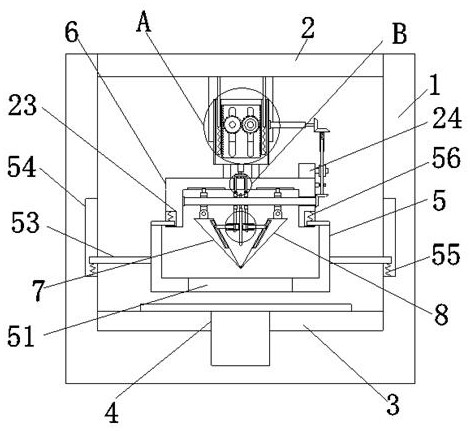
[0033] Example one, by Figure 1 to Figure 7 Given, the present invention includes a support frame 1, the top end of the support frame 1 is provided with a horizontal plate 2, the inner bottom end of the support frame 1 is provided with a bending table 3, and the bottom end of the bending table 3 and the support frame 1 is provided with a connecting Through the bending groove 4, the upper part of the bending table 3 is provided with a pressing plate 5, the upper part of the pressing plate 5 is connected with a mounting plate 6, and the upper part of the mounting plate 6 is connected with the horizontal plate 2 through a height adjustment mechanism, and the mounting plate 6 is inverted. The U-shaped structure, the lower part of the mounting plate 6 is provided with a bending plate 1 7 and a bending plate 2 8, the bottom ends of the bending plate 1 7 and the bending plate 2 8 are connected by hinges, and the bending plate 1 7 It is connected with the bending plate 2 8 by a spaci...

Embodiment 2

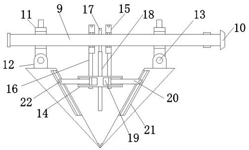
[0036] Embodiment 2, on the basis of Embodiment 1, by figure 1 , figure 2 , image 3 and Figure 7 Given, the spacing adjustment member includes an internal thread groove 19, a T-shaped screw 20, a sliding groove 21 and a sliding rod 22, and a sliding groove 21 is provided on the adjacent side of the bending plate 7 and the bending plate 2 8, and the rotating cylinder 14 The inner wall is symmetrically provided with an internal thread groove 19, the inner thread of the internal thread groove 19 is threadedly connected with a T-shaped screw 20, one end of the T-shaped screw 20 extends to the interior of the sliding groove 21, and the T-shaped screw 20 is provided with the sliding groove 21. The sliding rod 22 is slidably connected, the driver includes a motor 24, a turbine 25, a worm 26, a bevel gear 27 and a transmission part, the top of the mounting plate 6 is provided with a motor 24, the output shaft of the motor 24 is connected with a turbine 25, and the mounting plate ...

Embodiment 3

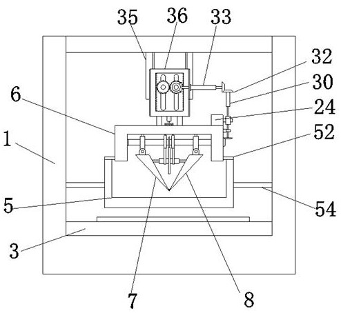
[0038] Embodiment 3, on the basis of Embodiment 1, by figure 1 , figure 2 , Figure 5 and Image 6 Given, the height adjustment mechanism includes a fixed plate 35, a height adjustment frame 36, a bevel gear five 37, a slot 38, a rotating shaft 39, a gear three 40, gear teeth 41 and a connecting piece, and the bottom end of the horizontal plate 2 is provided with a fixed Plate 35, a height adjustment frame 36 is arranged on one side of the fixed plate 35, a rotating shaft 39 is symmetrically installed on the side wall of the fixed plate 35, a slot 38 is symmetrically opened on the height adjustment frame 36, and one end of the rotating shaft 39 runs through the slot 38 Inside, and one end of the rotating shaft 39 is provided with a gear three 40, two gear three 40 are meshed and connected, one of the rotating shaft 39 is connected with the transmission part, the inner wall of the height adjustment frame 36 is provided with gear teeth 41 at equal distances, and the gear thre...


PUM


Abstract

The invention relates to the technical field of aluminum alloy ingot machining, discloses a bending device for aluminum alloy ingot machining and forming, and solves the problems that an aluminum alloy ingot needs to be manually pressed during bending, and bending heads of different sizes need to be repeatedly replaced when the aluminum alloy ingot needs to be bent into different angles, so that the bending efficiency is low. The device comprises a supporting frame, a transverse plate is arranged at the top end of the supporting frame, a bending table is arranged at the inner bottom end of the supporting frame, bending grooves which are communicated are formed in the bottom ends of the bending table and the supporting frame, a pressing plate is arranged above the bending table, a mounting plate is connected to the upper portion of the pressing plate, and the upper portion of the mounting plate is connected with the transverse plate through a height adjusting mechanism. The mounting plate is of an inverted U-shaped structure; through the design of the height adjusting mechanism and the pressing plate, pressing of the pressing plate on the aluminum alloy ingot is achieved, the bending stability of the aluminum alloy ingot is improved, deviation of the aluminum alloy ingot during bending is avoided, and the bending quality of the aluminum alloy ingot is improved.

Description

technical field [0001] The invention belongs to the technical field of aluminum alloy ingot processing, in particular to a bending device for processing and forming aluminum alloy ingots. Background technique [0002] Aluminum alloy is mixed with other metals in the state of high temperature liquid aluminum. After mixing evenly, it solidifies into a circular aluminum column in a columnar shape. During the production and transportation of aluminum alloy, in order to facilitate transportation, the aluminum column is generally extruded into an aluminum alloy ingot. However, Aluminum alloy ingots usually need to be bent when they are processed. [0003] However, manual pressing is required when bending the aluminum alloy ingot, resulting in a large labor investment. When the aluminum alloy ingot needs to be bent into different angles, it is necessary to repeatedly replace the bending heads of different sizes, which in turn results in low bending efficiency of the aluminum alloy ...

Claims


Application Information

Patent Timeline
IPC IPC(8): B21D11/00B21D11/22B21D37/04B21D37/00
CPCB21D11/00B21D11/22B21D37/04B21D37/00
Inventor 徐俊飞
Owner 江苏绿创新材料科技有限公司
Why Eureka
Try Eureka