
Coil stock dual-pressure automatic punching all-in-one machine

A dual-pressure, automatic punching technology, applied in metal processing and other directions, can solve the problems of punching positioning deviation, positioning error, and low punching efficiency.

Pending Publication Date: 2020-10-30
深圳市欣荣自动化智能设备有限公司
View PDF0 Cites 0 Cited by
  • Summary
  • Abstract
  • Description
  • Claims
  • Application Information

AI Technical Summary

Problems solved by technology

[0003] In the existing LPF punching production, the punching operation of the flexible circuit board is completed by manually picking and placing the sheet and then punching. However, manual handling of the sheet requires a lot of manpower and material resources, which is prone to punching positioning The phenomenon of deviation, and the punching efficiency is low, and the safety is lacking; and according to the design of some flexible circuit boards, the punching positions of the roll material are very dense, which makes the design and production of the punching die very difficult, and the processing of the punching die The cost is very high; on the market, the same roll-shaped material is generally put into different punching dies for punching operations, so as to complete the preparation of dense punching holes. However, due to the need to put the roll-shaped material into different punching dies In the process, it is inevitable that there will be positioning errors, resulting in a large increase in the number of defective products punched out, and the punching efficiency is very low

Method used


Image

  • Coil stock dual-pressure automatic punching all-in-one machine
  • Coil stock dual-pressure automatic punching all-in-one machine
  • Coil stock dual-pressure automatic punching all-in-one machine

Examples


Embodiment Construction

[0026] The following will clearly and completely describe the technical solutions in the embodiments of the present invention with reference to the accompanying drawings in the embodiments of the present invention. Obviously, the described embodiments are only some, not all, embodiments of the present invention. Based on the embodiments of the present invention, all other embodiments obtained by persons of ordinary skill in the art without making creative efforts belong to the protection scope of the present invention.

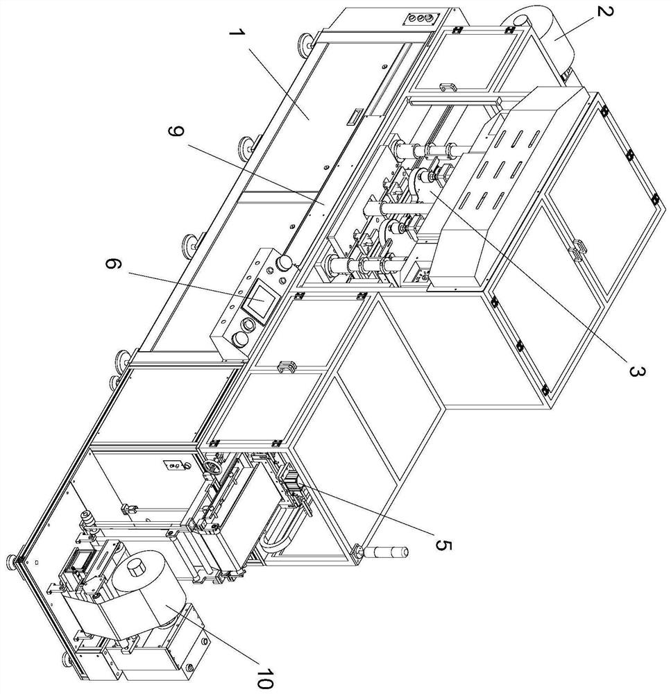
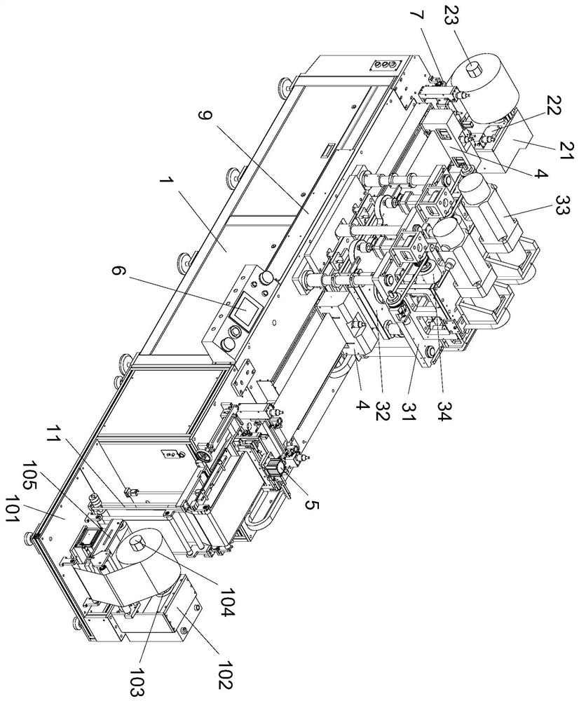
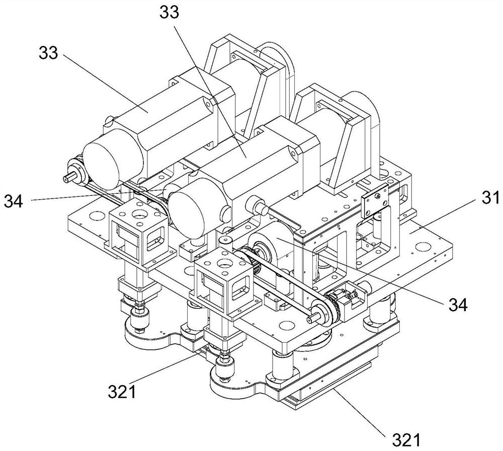
[0027] see Figure 1-8 , double-pressure automatic punching and cutting machine for roll material, including frame 1, unwinding device 2, double-pressure punching device 3, double-clamping and handling device 4, cutting device 5 and LPF are fixedly installed above the frame 1 The controller 6, the unwinding device 2, the dual-pressure punching device 3 and the cutting device 5 are set separately from left to right in turn; the dual-pressure punching device 3 i...


PUM


Abstract

The invention discloses a coil stock dual-pressure automatic punching all-in-one machine, and relates to the technical field of punching. The coil stock dual-pressure automatic punching all-in-one machine comprises a rack, a coil stock feeding device, a dual-pressure punching device, a dual-clamping carrying device, a cutting device and an LPF controller are fixedly arranged above the rack, and the coil stock fe device, the dual-pressure punching device and the cutting device are sequentially arranged from left to right in a separated manner; the dual-pressure punching device comprises a punching frame, punching dies, punching motors and lifters; the two punching dies are arranged in a left-right separated manner, each punching die comprises an upper die and a lower die, the two punching motors and the two lifters are arranged in a left-right separated manner, the punching frame and the lower dies are fixedly arranged at the upper end of the rack, the punching motors and the lifters are fixedly arranged at the upper end of the punching frame, and the punching motors correspondingly drive the upper dies to vertically move through the lifters; the LPF controller correspondingly controls the coil stock feeding device, the punching motors, the dual-clamping carrying device and the cutting device to work; and the punching precision is higher, and the efficiency is higher.

Description

technical field [0001] The invention relates to the technical field of punching and cutting, in particular to an integrated double-pressure automatic punching and cutting machine for roll materials. Background technique [0002] At present, in the flexible circuit board manufacturing (FPC) industry, roll materials such as cover film and PI are generally used, and the roll materials need to be punched. The punching equipment based on the LPF system control is generally used on the market to cut the roll materials. shape material for punching. [0003] In the existing LPF punching production, the punching operation of the flexible circuit board is completed by manually picking and placing the sheet and then punching. However, manual handling of the sheet requires a lot of manpower and material resources, which is prone to punching positioning The phenomenon of deviation, and the punching efficiency is low, and the safety is lacking; and according to the design of some flexibl...

Claims


Application Information

Patent Timeline
IPC IPC(8): B26D9/00B26F1/40B26F1/02B26D1/08B26D7/06B26D7/32B26D7/02
CPCB26D1/08B26D7/02B26D7/06B26D7/0616B26D7/32B26D9/00B26F1/02B26F1/40
Inventor 黄涛
Owner 深圳市欣荣自动化智能设备有限公司
Learn More