A continuous punching machine for birdcages
A punching machine and birdcage technology, which is applied in the field of punching machines, can solve the problems of large labor consumption, low work efficiency, uneven punching, etc., and achieve the effects of improving efficiency, reducing workload, and saving manpower consumption
- Summary
- Abstract
- Description
- Claims
- Application Information
AI Technical Summary
Problems solved by technology
Method used
Image
Examples
Embodiment 1
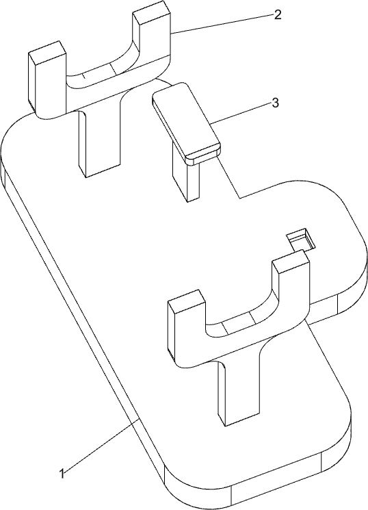
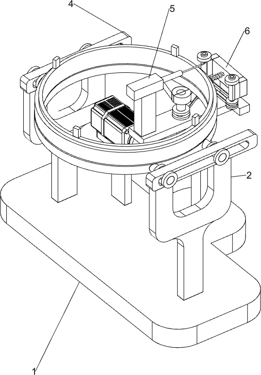
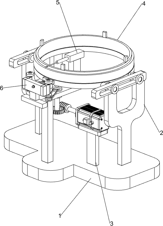
[0047] A continuous punching machine for birdcages, such as Figure 1-3 As shown, it includes a base 1, a support frame 2, a support 3, a transmission mechanism 4 and a drilling mechanism 5, the top left and right sides of the base 1 are provided with a support frame 2, and the right part of the top front side of the base 1 is provided with a support 3 A transmission mechanism 4 is connected between the top of the support frame 2 and the support 3, and a drilling mechanism 5 is installed in the middle of the transmission mechanism 4.
[0048] When people need to punch a birdcage, people place the birdcage on the parts of the transmission mechanism 4, start the parts of the transmission mechanism 4, make the parts of the transmission mechanism 4 constantly rotate to drive the birdcage to rotate, and simultaneously start the drilling mechanism 5 The parts of the drilling mechanism 5 are used to punch the birdcage. When people no longer need to punch the birdcage, people can clos...
Embodiment 2
[0050] On the basis of Example 1, such as Figure 4-6 As shown, the transmission mechanism 4 includes a motor 41, a worm screw 42, a pillar 43, a transmission platform 44, a worm wheel 45, a transmission connecting rod 46, a bump 47, a sliding block 48, a first fixing bolt 49, a sliding chassis 410 and a rotating disk 411 , the top of the bracket 3 is provided with a motor 41, the output shaft of the motor 41 is provided with a worm 42, the top front side of the base 1 is provided with a pillar 43, the top of the pillar 43 is provided with a transmission platform 44, and the top rear side of the transmission platform 44 is opened. There is a groove, the groove is connected with the drilling mechanism 5, and the middle part of the transmission platform 44 is connected with a transmission connecting rod 46 in a rotating manner. The top is provided with projection 47, and the top of support frame 2 is provided with slide block 48, and the middle part of slide block 48 all has a s...
Embodiment 3
[0055] On the basis of Example 2, such as Figure 7As shown, the continuous punching mechanism 6 is also included, and the continuous punching mechanism 6 includes the first runner 61, the first belt 62, the second runner 63, the fixed block 64, the movable connecting rod 65, the second fixed bolt 66 , spring 67, push rod 68, push block 69 and the second belt 610, the front side of transmission platform 44 is provided with fixed block 64, and the left and right sides of fixed block 64 rear parts are all rotationally connected with movable connecting rod 65, and movable connection The top of the bar 65 is provided with a second fixing bolt 66, and the lower side of the right side movable connecting rod 65 and the upper side of the transmission connecting rod 46 are all provided with a first runner 61, and the two first runners 61 are wound with a The first belt 62 and the bottom of the movable connecting rod 65 are provided with a second runner 63, a second belt 610 is wound be...
PUM
 Abstract
Description
Claims
Application Information
 - R&D
- Intellectual Property
- Life Sciences
- Materials
- Tech Scout
- Unparalleled Data Quality
- Higher Quality Content
- 60% Fewer Hallucinations
Browse by: Latest US Patents, China's latest patents, Technical Efficacy Thesaurus, Application Domain, Technology Topic, Popular Technical Reports.
© 2025 PatSnap. All rights reserved.Legal|Privacy policy|Modern Slavery Act Transparency Statement|Sitemap|About US| Contact US: help@patsnap.com


