Film continuous punching device

A punching device and film technology, applied in packaging, transportation and packaging, paper/cardboard containers, etc., can solve the problems of slow punching speed, complex structure, and feeding stoppage of the bag making machine.

Pending Publication Date: 2021-03-09
骏业塑胶(深圳)有限公司
View PDF6 Cites 0 Cited by
  • Summary
  • Abstract
  • Description
  • Claims
  • Application Information

AI Technical Summary

Problems solved by technology

Because the punching punch and the zigzag punching knife need to stop the bag making machine, the punching punch or the punching knife will penetrate the film from the upper surface of the film and insert it into the die below the film. Punching is carried out inside or in the hole of the base of the punching knife, and it is impossible to carry out punching work on a bag making machine that does not stop feeding.
[0003] The Chinese patent application number CN201420017003.1 discloses a film continuous punching mechanism, which includes a bracket and a row of punchers arranged horizontally in the middle of the left and right bracket wall panels. The puncher includes a punch, a punch driver and a bottom die. The punch is connected to the drive shaft of the punch driver, the bottom mold is fixed under the punch, the bottom mold is provided with a punching hole and the punch is directly opposite, and the punch driver adopts the structure that the electromagnetic coil absorbs the iron core to reciprocate. The film continuous punching mechanism can have a high punching speed, but its structure is relatively complicated, and the punching speed is slow

Method used


Image

  • Film continuous punching device
  • Film continuous punching device

Examples


Embodiment Construction

[0019] Below in conjunction with specific embodiment and accompanying drawing, the present invention is further elaborated and illustrated:

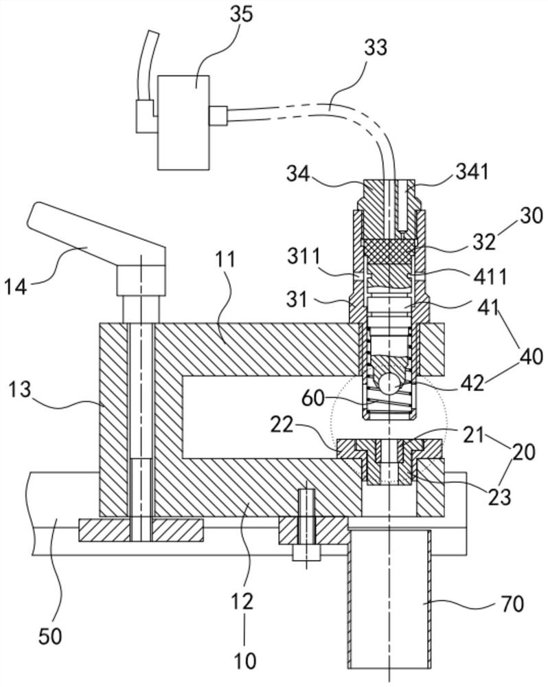
[0020] Please refer to figure 1 , a film continuous punching device, including a bracket 10, a bottom knife device 20, a pneumatic piston device 30, and a punching ball device 40.

[0021] The bracket 10 includes an upper support portion 11 , a lower support portion 12 and a connecting portion 13 connecting the upper support portion 11 and the lower support portion 12 . Wherein, the bottom knife device 20 is arranged on the lower supporting part 12 , the pneumatic piston device 30 is arranged on the upper supporting part 11 , and the punching ball device 40 is opposite to the bottom knife device 20 up and down. In this embodiment, the bracket 10 is in the shape of "匸".

[0022] The support 10 is fixed on the guide rail 50 by the handle screw 14, and the guide rail 50 is fixed on the frame of the bag making machine. The locking nut is ...


PUM


Abstract

The invention discloses a film continuous punching device. The film continuous punching device comprises a support, a dead knife device arranged on the support, a pneumatic piston device and a punching ball device, and the dead knife device comprises a punching dead knife; the pneumatic piston device comprises a fixing sleeve arranged on the support, a piston arranged in the fixing sleeve and an air pipe connected to the upper end of the fixing sleeve, and the lower end of the fixing sleeve is open; the punching ball device is arranged in the fixing sleeve and comprises a ball seat and a punching ball body, the punching ball body is arranged at one end of the ball seat, and the other end of the ball seat abuts against the piston; the air pipe provides airflow to push the piston, and the piston moves along the fixing sleeve and pushes the ball seat and the punching ball body, so that the punching ball body moves out of the fixing sleeve from the opening and hit on the punching dead knife; and a return piece is further included, and the punching ball device is reset through deformation of the return piece in the process that the punching ball device moves along the fixing sleeve. Thefilm continuous punching device can be used for continuously and quickly punching a film.

Description

technical field [0001] The invention relates to the technical field of plastic film processing, in particular to a film continuous punching device. Background technique [0002] Now the plastic film bag making machine generally uses a cylinder-driven convex and concave die puncher and a zigzag punching knife to punch holes on the plastic film. Because the punching punch and the zigzag punching knife need to stop the bag making machine, the punching punch or the punching knife will penetrate the film from the upper surface of the film and insert it into the die below the film. If punching is carried out inside or in the hole of the punching knife base, it is impossible to punch holes on a bag making machine that does not stop feeding. [0003] The Chinese patent application number CN201420017003.1 discloses a film continuous punching mechanism, including a bracket and a row of punchers arranged horizontally in the middle of the left and right bracket wallboards. The puncher ...

Claims


Application Information

Patent Timeline
Patent Type & Authority Applications(China)
IPC IPC(8): B31B70/14B31B70/00B31B160/10
CPCB31B70/14B31B70/006B31B2160/10
Inventor 尚飞翁玮泽房稳桥赵枫李林
Owner 骏业塑胶(深圳)有限公司
Why Eureka
Try Eureka