A punching device with a buffer structure

A technology of punching device and buffer structure, applied in the field of punching device, can solve the problems of strong bouncing, impact and vibration of punching machine, affecting the accuracy and service life of punching machine, damage of punching machine and die, etc. Reasonable and avoid the effect of causing damage

Active Publication Date: 2022-08-09
武汉威普泰科技有限公司
View PDF0 Cites 0 Cited by
  • Summary
  • Abstract
  • Description
  • Claims
  • Application Information

AI Technical Summary

Problems solved by technology

[0003] In the processing and production of auto parts, punching of rolling parts is often involved. In the punching process, when the rolling parts break, the hydraulic machine suddenly unloads and loses the load, so that the load of the workpiece disappears suddenly. The liquid compression energy in the oil cylinder and the fuselage The elastic deformation can be released sharply, causing the workpiece to suddenly lose control at the moment of fracture, and to punch down at a great speed, which will have a huge impact on the buffer cylinder. The stamping machine will not only produce huge and strong bounce, shock and vibration, but will noise, and cause damage to both the punching machine and the mold, which seriously affects the accuracy and service life of the punching machine. Therefore, we propose a punching device with a buffer structure

Method used


Image

  • A punching device with a buffer structure
  • A punching device with a buffer structure
  • A punching device with a buffer structure

Examples


Embodiment Construction

[0027] The technical solutions in the embodiments of the present invention will be clearly and completely described below with reference to the accompanying drawings in the embodiments of the present invention. Obviously, the described embodiments are only a part of the embodiments of the present invention, but not all of the embodiments. Based on the embodiments of the present invention, all other embodiments obtained by those of ordinary skill in the art without creative efforts shall fall within the protection scope of the present invention.

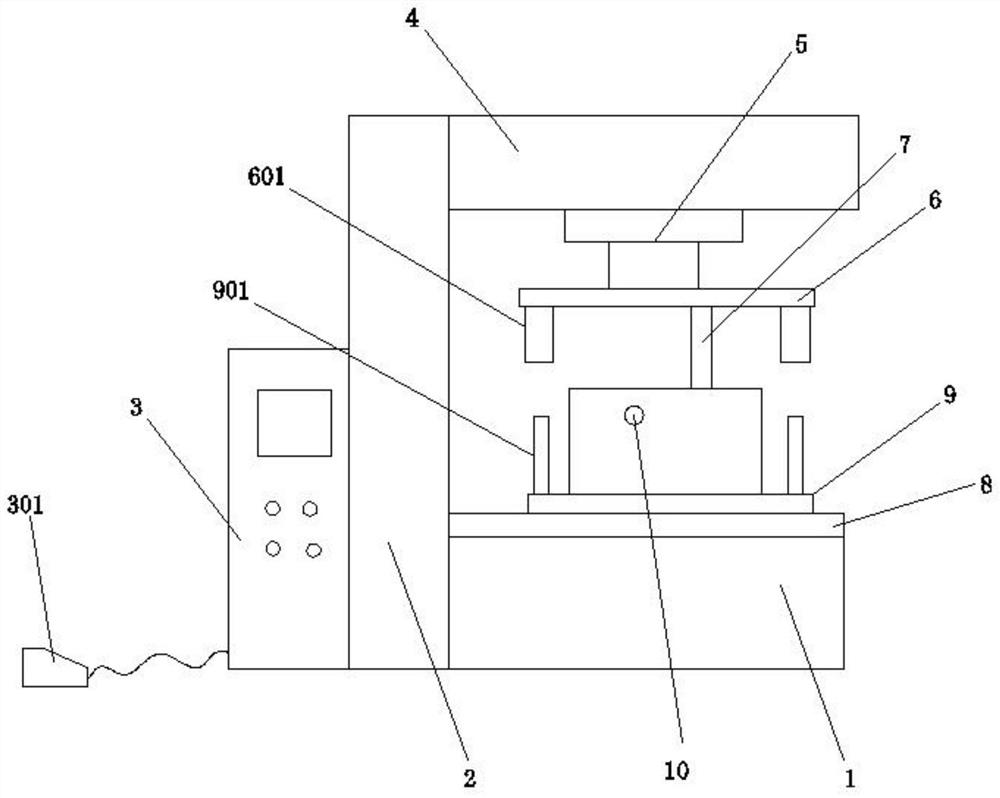
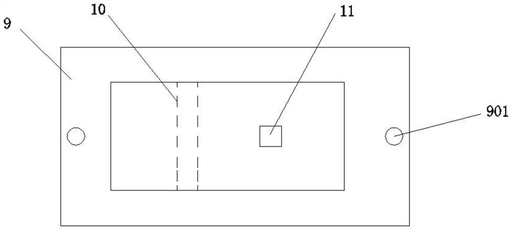
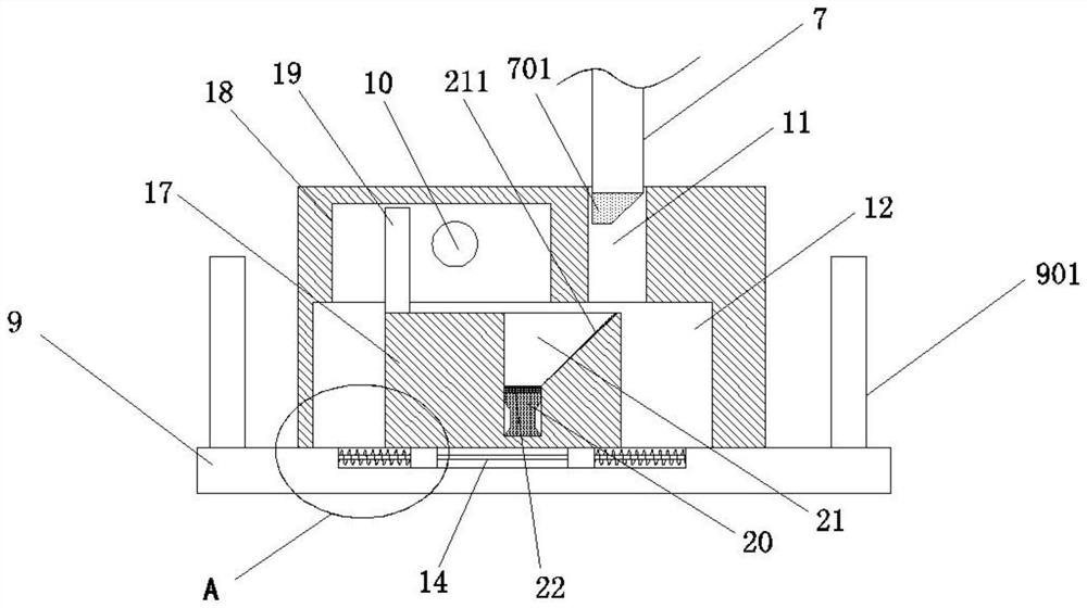
[0028] see Figure 1-6 As shown, this embodiment is a punching device with a buffer structure, including a machine tool 1, a support frame 2 is connected to the left side of the machine tool 1, an electric control box 3 is connected to the left side of the support frame 2, and a right side of the support frame 2 is connected The top of the wall is connected with a fixed base 4, the bottom of the fixed base 4 is connected with a cylind...


PUM


Abstract

The invention discloses a punching device with a buffer structure, comprising a machine tool, a support frame is connected to the left side of the machine tool, an electric control box is connected to the left side of the support frame, a fixing seat is connected to the top of the right side wall of the support frame, and the fixing seat The bottom of the machine tool is connected with an air cylinder, the bottom of the cylinder is connected with an upper die base, the bottom of the upper die base is connected with a pressure column, the top of the machine tool is connected with a workbench, the top of the workbench is connected with a lower die base, and the lower die base is located in the upper die base. The present invention has reasonable structure design and simple operation, and can continuously punch the workpiece, the pressing block descends along the buffer cavity to squeeze the buffer liquid, the concave part on the inner tube is slightly deformed by pressing outward, and at the same time, the hoop is reinforced. The bulge of the inner tube is deformed by the outward pressing of the inner tube, and an inward tightening force is generated. The tightening force can offset part of the liquid pressure, achieve a good buffering effect, and avoid damage to stamping equipment and molds. , which is beneficial to improve the service life of the device.

Description

technical field [0001] The invention relates to the technical field of punching devices, in particular to a punching device with a buffer structure. Background technique [0002] Stamping die is a special process equipment for processing materials into parts in cold stamping processing, called cold stamping die. Stamping is a pressure processing method that uses a die installed on a press to apply pressure to a material at room temperature to separate or plastically deform it to obtain the required parts. [0003] In the processing and production of auto parts, the punching of rolling parts is often involved. In the punching process, the hydraulic press is suddenly unloaded and unloaded at the moment when the rolling parts are broken, so that the load of the workpiece suddenly disappears, and the liquid compression energy in the cylinder and the fuselage The elastic deformation can be released sharply, causing the workpiece to suddenly lose control of the punch at the momen...

Claims


Application Information

Patent Timeline
Patent Type & Authority Patents(China)
IPC IPC(8): B21D28/14B21D37/12F16F15/02F16F15/023F16F15/04F16F15/06
CPCB21D28/14B21D37/12F16F15/022F16F15/0232F16F15/06F16F15/046
Inventor 鄢绪波
Owner 武汉威普泰科技有限公司
Why Eureka
Try Eureka