
Novel structure for reducing stress concentration of pull rod of injection molding machine

A stress concentration and injection molding machine technology, applied in the field of injection molding machine tie rod components, can solve problems such as tie rod fatigue, resistance to stress deformation of tie rod c, and thread deviation of tie rods, so as to reduce the probability of loosening, avoid slight deviation, and improve service life Effect

Inactive Publication Date: 2020-10-30
NINGBO HAIDA PLASTIC MACHINERY
View PDF7 Cites 0 Cited by
  • Summary
  • Abstract
  • Description
  • Claims
  • Application Information

AI Technical Summary

Problems solved by technology

[0003] Chinese Patent Document No. 200720110982.5 proposes an "injection molding machine tie rod structure". Although it provides a structure that reduces the stress concentration of the tie rods, this structure has limitations, such as Figure 9 , because the fixed plate a is bent and deformed, and the mold mounting surface is also deformed, so the fixed plate a and the tie rod c interfere in their positioning parts, hindering the stress deformation of the tie rod c, so that the bending stress is concentrated. At the same time, the existing injection molding machine tie rod mechanism , the tie rod and the tie rod nut basically provide the tensile load through thread engagement. Plate deformation, resulting in uneven distribution of axial load on each button thread, especially when the fixed plate is bent and deformed, the shear force acting on the threaded part of the tie rod will cause a slight offset of the threaded part of the tie rod, which will cause the nut to exist over time. Looseness will also cause the tie rod to fatigue and eventually break and fail. For this reason, we propose a new structure for the injection molding machine tie rod to reduce stress concentration

Method used


Image

  • Novel structure for reducing stress concentration of pull rod of injection molding machine
  • Novel structure for reducing stress concentration of pull rod of injection molding machine
  • Novel structure for reducing stress concentration of pull rod of injection molding machine

Examples


Embodiment Construction

[0025] The following will clearly and completely describe the technical solutions in the embodiments of the present invention with reference to the accompanying drawings in the embodiments of the present invention. Obviously, the described embodiments are only some, not all, embodiments of the present invention. Based on the embodiments of the present invention, all other embodiments obtained by persons of ordinary skill in the art without making creative efforts belong to the protection scope of the present invention.

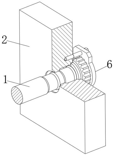
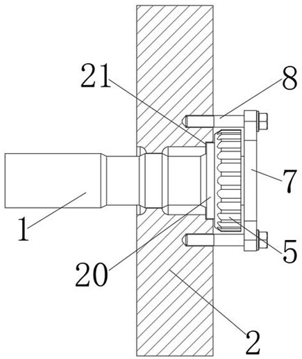
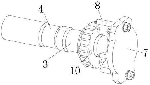
[0026] see Figure 1-9 , the injection molding machine tie rod in the figure shows a new structure for reducing stress concentration, including a tie rod body 1, one end of the tie rod body 1 is connected with a fixing plate 2, and a section of the outer side of the tie rod body 1 located in the fixing plate 2 is provided with threads for reducing The first unloading groove 3 that concentrates the stress, and the outside of the tie rod body 1 is provided with ...


PUM


Abstract

The invention discloses a novel structure for reducing stress concentration of a pull rod of an injection molding machine. The novel structure comprises a pull rod body. A fixed plate is connected toone end of the pull rod body in a penetrated mode. A first unloading groove for reducing concentrated stress of a thread section is formed in the outer side of the section, located in the fixed plate,of the pull rod body, and a second unloading groove for reducing stress concentration of the pull rod due to deformation interference of the fixed plate is formed in the outer side of the pull rod body. According to the novel structure, through the first unloading groove and the second unloading groove designed in the outer side of the pull rod body, stress concentration of the thread section isreduced, stress concentration of the fixed plate and the pull rod due to deformation interference of the fixed plate is reduced, cracks, even breakage and other failure phenomena caused by fatigue generated during long-term use of the pull rod body are avoided, meanwhile, loading force on a pull rod nut and a screw thread is dispersed effectively, a slight shift of the thread part of the pull rodis avoided, the looseness probability of the nut is lowered, and the service life of the pull rod body is prolonged.

Description

technical field [0001] The invention relates to the technical field of injection molding machine tie rod components, in particular to a new structure for reducing stress concentration of an injection molding machine tie rod. Background technique [0002] The tie rod is an important high-rigidity elastic part for the clamping mechanism of the injection molding machine to generate the clamping force, which is directly related to the reliable operation of the clamping mechanism and its service life. If the tie rod of the clamping mechanism is improperly designed, the thread of the tie rod is prone to failure phenomena such as stress concentration, cracks or even breakage. The tie rod is the backbone of the injection molding machine. By compressing the mold, stretching the tie rod, and finally locking the mold. Due to the stretching of the tie rod, the tie rod nut is compressed, so that the fixing plate will be bent and deformed, and the tie rod will be bent and deformed accord...

Claims


Application Information

Patent Timeline
Patent Type & Authority Applications(China)
IPC IPC(8): B29C45/17B29C45/66
CPCB29C45/1747B29C45/66
Inventor 毛显波
Owner NINGBO HAIDA PLASTIC MACHINERY
Learn More