Clamping structure of hoisting machine
A hoisting and clamping technology, applied in mechanical equipment, load hanging elements, springs/shock absorbers, etc., can solve the problem that the clamping structure cannot be hoisted, the height cannot be adjusted according to the demand, and the clamping angle cannot be adjusted. question
- Summary
- Abstract
- Description
- Claims
- Application Information
AI Technical Summary
Problems solved by technology
Method used
Image

Examples
specific Embodiment approach 1
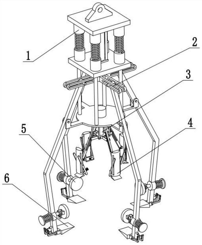
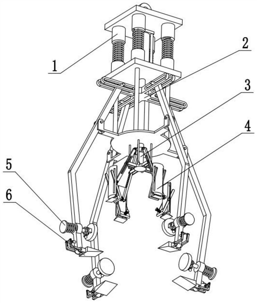
[0028] Combine below Figure 1-10 This embodiment is described. The present invention relates to the technical field of clamping mechanism, more specifically, a clamping structure of a hoisting machine, including a shock-absorbing buffer suspension mechanism 1, an outer wall clamping drive mechanism 2, and an inner wall clamping drive mechanism. 3. Inner wall fitting supporting mechanism 4, horizontal stable clamping block 5 and bottom supporting telescopic mechanism 6. The inner wall fitting supporting mechanism 4, horizontal stabilizing clamping block 5 and bottom supporting telescopic mechanism 6 are all provided with four The four bottom supporting telescopic mechanisms 6 are all fixedly connected to the outer wall clamping drive mechanism 2, the outer wall clamping drive mechanism 2 is fixedly connected to the shock-absorbing buffer suspension mechanism 1, and the inner wall clamping drive mechanism 3 is fixedly connected to the outer wall On the clamping drive mechanism ...
specific Embodiment approach 2
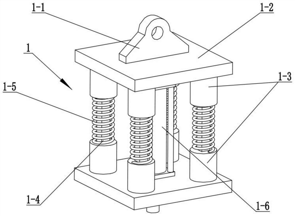
[0031] Combine below Figure 1-10Describe this embodiment, this embodiment will further explain the first embodiment, the shock-absorbing buffer suspension mechanism 1 includes a suspension orifice 1-1, a connecting plate 1-2, a sliding sleeve 1-3, and an intermediate sliding rod 1 -4, shock absorbing spring 1-5 and driving cylinder 1-6, two connecting flat plates 1-2 are provided with, four sliding sleeves 1-3 are all arranged on the two connecting flat plates 1-2, four intermediate sliding sleeves The upper and lower ends of the rod 1-4 are respectively slidably connected to the upper and lower corresponding sliding sleeves 1-3, the hanging orifice 1-1 is fixedly connected to the connecting plate 1-2 at the upper end, and the driving cylinder 1-6 is fixed Connected to the connection plate 1-2 at the lower end, the four damping springs 1-5 are sleeved on the four middle sliding rods 1-4 respectively.
[0032] When lifting and putting down the article, the damping spring 1-5 ...
specific Embodiment approach 3
[0034] Combine below Figure 1-10 Describe this embodiment, this embodiment will further explain the second embodiment, the outer wall clamping drive mechanism 2 includes a suspension rod 2-1, a suspension plate 2-2, a drive motor 2-3, and a clamping upper arm 2-4 And the cross lifting slideway 2-5, the cross lifting slideway 2-5 is fixedly connected on the telescopic shaft of the drive cylinder 1-6, and the tops of the four suspension rods 2-1 are fixedly connected to the bottom end of the suspension rod 2-1, and the suspension The board 2-2 is fixedly connected to the bottom ends of the four suspension rods 2-1, the drive motor 2-3 is fixedly connected to the suspension board 2-2, and the tops of the four clamping upper arms 2-4 are all slidably connected to the cross lifting slideway On 2-5, the middle parts of four clamping upper arms 2-4 are all rotatably connected on the suspension plate 2-2.
[0035] The driving cylinder 1-6 drives the cross lifting slideway 2-5 to go ...
PUM
 Abstract
Description
Claims
Application Information
 - R&D
- Intellectual Property
- Life Sciences
- Materials
- Tech Scout
- Unparalleled Data Quality
- Higher Quality Content
- 60% Fewer Hallucinations
Browse by: Latest US Patents, China's latest patents, Technical Efficacy Thesaurus, Application Domain, Technology Topic, Popular Technical Reports.
© 2025 PatSnap. All rights reserved.Legal|Privacy policy|Modern Slavery Act Transparency Statement|Sitemap|About US| Contact US: help@patsnap.com