
Driving structure, driving device and electronic equipment

A driving device and driving structure technology, applied in focusing device, installation, circuit, etc., can solve the problems of slow focusing speed, influence of imaging effect, position deviation, etc., and achieve the effect of high focusing accuracy

Pending Publication Date: 2020-10-30
NEW SHICOH MOTOR CO LTD
View PDF0 Cites 4 Cited by
  • Summary
  • Abstract
  • Description
  • Claims
  • Application Information

AI Technical Summary

Problems solved by technology

[0003] The defect of the above-mentioned driving structure is that: the driving methods of the two groups of lenses each cause positional deviation in the direction of the optical axis, which affects the imaging effect, and cannot meet higher requirements for precision, and its focusing speed is relatively slow

Method used


Image

  • Driving structure, driving device and electronic equipment
  • Driving structure, driving device and electronic equipment
  • Driving structure, driving device and electronic equipment

Examples


Embodiment 1

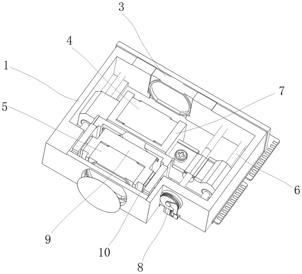
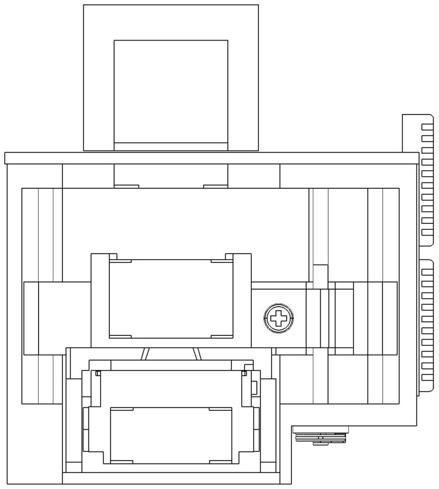
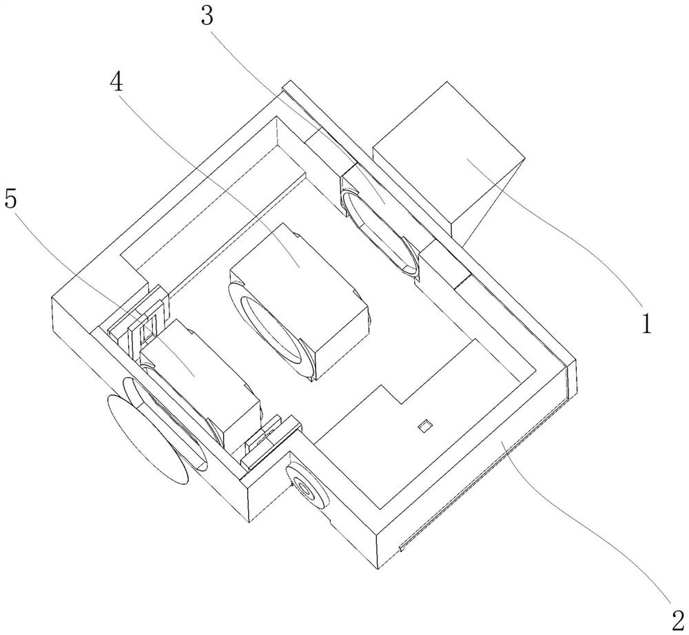
[0055] A driving structure, comprising a frame (1), a slide rail (6) is provided inside the frame (1), a first carrier (7) is movably mounted on the slide rail (6), and the first carrier (7) ) is provided with a piezoelectric motor on the side, and the piezoelectric motor drives the first carrier (7) to move along the slide rail (6);

[0056] see figure 1 , In this embodiment, it is assumed that the installation position of the prism (2) is the front side, and the installation position of the third lens mounting body (5) is the rear side.

[0057] A second lens mounting body (4) is fixed on the front side of the first carrier (7);

[0058] A continuous zoom motor and a second carrier (9) are provided on the rear side of the first carrier (7), and the continuous zoom motor is connected to the second carrier (9) and drives the second carrier (9) and the third lens mounting body (5) MOVE.

[0059]The side of the frame (1) is provided with an installation groove (101), the firs...

Embodiment 2

[0071] A driving device has the driving structure described in Embodiment 1. In this embodiment, other structures of the driving device are the same as those of the prior art, so no detailed description is given here.


PUM


Abstract

The invention discloses a driving structure which comprises a frame, and a carrier assembly and a driving assembly are arranged in the frame. The carrier assembly comprises a first carrier and a second carrier arranged on the first carrier. The driving assembly comprises a first driving device and a second driving device, the first driving device is installed in the frame, the output end of the first driving device is connected with and drives the first carrier, the second driving device is installed on the first carrier, and the second driving device is connected with and drives the second carrier. The combination of a first driving motor and a second driving motor of different types is adopted to replace a traditional continuous zooming motor driving structure, and the focusing precisionis higher.

Description

technical field [0001] The invention relates to the field of periscope motors, in particular to a driving structure, a driving device and electronic equipment. Background technique [0002] Most of the existing continuous zoom driving mechanisms are a combined structure of two lenses, or a combined structure containing three lenses, wherein at least two lenses in such a driving mechanism are movable, and the driving methods between them are all They are driven separately; in the existing driving mechanism for realizing the continuous zoom function, two driving mechanisms are respectively used for the driving, generally the same type of driving method. [0003] The defect of the above-mentioned driving structure is that: the driving modes of the two groups of lenses each cause a positional deviation in the direction of the optical axis, which affects the imaging effect, cannot meet higher requirements for precision, and has a relatively slow focusing speed. Contents of the ...

Claims


Application Information

Patent Timeline
Patent Type & Authority Applications(China)
IPC IPC(8): G02B7/09G03B13/36
CPCG02B7/09G03B13/36G02B7/02H01F7/081H01F7/128H01F7/16
Inventor 王在伟
Owner NEW SHICOH MOTOR CO LTD
Learn More