Light irradiation device

A light irradiation device and light beam technology, applied in optics, optical components, instruments, etc., can solve problems such as the inability to adjust the angle of the outgoing light and uneven energy

Active Publication Date: 2020-10-30
SHANGHAI MICRO ELECTRONICS EQUIP (GRP) CO LTD
View PDF37 Cites 0 Cited by
  • Summary
  • Abstract
  • Description
  • Claims
  • Application Information

AI Technical Summary

Problems solved by technology

Since the direction of the beam reflected by the trough mirror is fixed, the angle of the light emitted by the light irradiation device cannot be adjusted; the energy distribution of the light emitted by the light outlet is Gaussian distribution, resulting in uneven energy received by the light receiving surface

Method used


Image

  • Light irradiation device
  • Light irradiation device
  • Light irradiation device

Examples


Embodiment Construction

[0030] The present invention will be further described in detail below in conjunction with the accompanying drawings and embodiments. It should be understood that the specific embodiments described here are only used to explain the present invention, but not to limit the present invention. In addition, it should be noted that, for the convenience of description, only some structures related to the present invention are shown in the drawings but not all structures.

[0031] Terms used in the embodiments of the present invention are only for the purpose of describing specific embodiments, and are not intended to limit the present invention. It should be noted that the orientation words such as "up", "down", "left", and "right" described in the embodiments of the present invention are described from the angles shown in the drawings, and should not be interpreted as a reference to the implementation of the present invention. Example limitations. Also in this context, it also nee...


PUM


Abstract

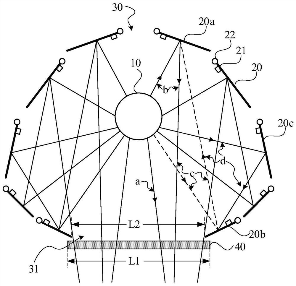
The invention discloses a light irradiation device. The device comprises a linear light source, and a number of reflection units which surround the linear light source to form a reflection cavity, thereflection cavity comprises a light outlet, and part of light beams emitted by the linear light source are reflected by at least one reflection unit and then emitted from the light outlet; the devicefurther comprises a plurality of first detection units which are used for measuring incident angles and first energy distribution of the light beams entering the corresponding reflection units, a plurality of rotating units which are used for driving the reflection units to rotate, a second detection unit which is used for measuring the emergence angle and the second energy distribution of the emergent light beams of the light outlet, and a control unit which is used for acquiring data of the incident angle, the first energy distribution, the emergence angle and the second energy distribution, and controlling the rotating units to rotate the reflection units according to the preset emergence angle, the preset energy distribution and the data, so that the emergent light beams are emergentaccording to the preset emergence angle and the preset energy distribution. According to the technical scheme, the emergent angle and the energy distribution of the emergent light beams can be adjusted, so that the requirements of various application scenes are met.

Description

technical field [0001] Embodiments of the present invention relate to light beam adjustment technology, and in particular, to a light irradiation device. Background technique [0002] In nature, because many materials will change in shape and properties under light, light irradiation devices are widely used in technical fields such as photo-alignment, curing, printing, and photo-cleaning. [0003] Existing light irradiation devices generally emit light beams through a line light source, and reflect the light beams to the light outlet through a groove-shaped reflector to exit. Since the direction of the beam reflected by the trough mirror is fixed, the angle of the light emitted by the light irradiation device cannot be adjusted; the energy distribution of the light emitted by the light outlet is Gaussian distribution, resulting in uneven energy received by the light receiving surface. Contents of the invention [0004] An embodiment of the present invention provides a lig...

Claims


Application Information

Patent Timeline
Patent Type & Authority Applications(China)
IPC IPC(8): G02B26/08G02B26/02
CPCG02B26/0816G02B26/02
Inventor 许凯迪
Owner SHANGHAI MICRO ELECTRONICS EQUIP (GRP) CO LTD
Why Eureka
Try Eureka