
Automobile part pressure pulsation test device

A pressure pulsation and test device technology, applied in the testing of machine/structural components, measuring devices, vibration testing, etc., can solve the problems of waste of energy resources, high cost, complex equipment, etc., to achieve energy saving, low cost, structural simple effect

Active Publication Date: 2022-01-28
SUZHOU YINGTEMO AUTOMOBILE TECH CO LTD
View PDF19 Cites 0 Cited by
  • Summary
  • Abstract
  • Description
  • Claims
  • Application Information

AI Technical Summary

Problems solved by technology

[0003] In the traditional pulsation test device, the power of the heater is often fixed, and the excess energy is taken away by the heat exchanger to control the temperature in the system. This method is not only complicated in structure, but also wastes a lot of energy resources
Referring to patent CN202022158506.9, the existing pressure pulsation test system uses an electric vibration table as the vibration generating equipment, and is composed of a linear motion drive mechanism piston and a hydraulic cylinder system. The equipment is complex, the cost is high, and the flow and temperature cannot be achieved. adjust

Method used


Image

  • Automobile part pressure pulsation test device
  • Automobile part pressure pulsation test device
  • Automobile part pressure pulsation test device

Examples


Embodiment Construction

[0024] The following is a further non-limiting detailed description of the technical solution of the invention in combination with preferred embodiments and accompanying drawings. In describing the present invention, it should be understood that the terms "center", "longitudinal", "transverse", "length", "width", "thickness", "upper", "lower", "front", " Back", "Left", "Right", "Vertical", "Horizontal", "Top", "Bottom", "Inner", "Outer", "Clockwise", "Counterclockwise", "Axial", The orientation or positional relationship indicated by "radial direction", "circumferential direction", etc. is based on the orientation or positional relationship shown in the drawings. In addition, the terms "first" and "second" are used for descriptive purposes only, and cannot be interpreted as indicating or implying relative importance or implicitly specifying the quantity of indicated technical features. Thus, the features defined as "first" and "second" may explicitly or implicitly include at ...


PUM


Abstract

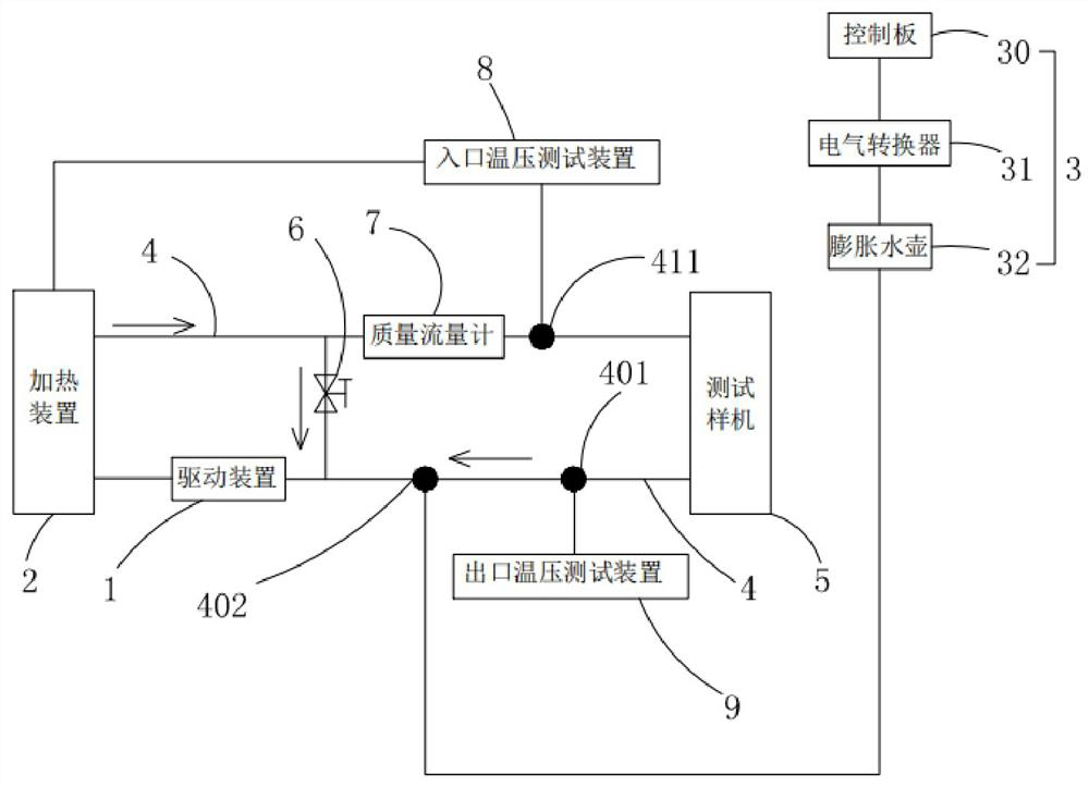
The invention discloses an automobile part pressure pulsation test device which comprises a driving device and a pressure pulsation device which are connected with each other through a pipeline, the driving device and the pressure pulsation device are both connected with a test prototype, and the test device further comprises a heating device for controlling the temperature of cooling liquid and a balance valve for adjusting the flow of the cooling liquid. One end of the heating device is connected with the driving device, the other end of the heating device is connected with the test prototype, one end of the balance valve is connected between the heating device and the test prototype, and the other end of the balance valve is connected between the driving device and the test prototype. The invention discloses the automobile part pressure pulsation test device, which adopts a balance valve to realize flow regulation of a system, adopts a temperature control closed loop to realize temperature control of the system, and is simple in structure and low in cost.

Description

technical field [0001] The invention relates to a pressure pulsation test device for automobile parts. Background technique [0002] With the rapid development of the automobile industry, the demand for automobile parts is also increasing. Automobile motors, controllers and other parts are important parts of automobiles. Their functions must meet the requirements before they can be used. Therefore, when using these Performance testing is required before parts are delivered. [0003] In the traditional pulsation test device, the power of the heater is often fixed, and the excess energy is taken away by the heat exchanger to control the temperature in the system. This method is not only complicated in structure, but also wastes a lot of energy resources. Referring to patent CN202022158506.9, the existing pressure pulsation test system uses an electric vibration table as the vibration generating equipment, and is composed of a linear motion drive mechanism piston and a hydraul...

Claims


Application Information

Patent Timeline
Patent Type & Authority Applications(China)
IPC IPC(8): G01M7/02G01M17/007
CPCG01M7/02G01M17/007
Inventor 高永兴胡佑明邵添羽
Owner SUZHOU YINGTEMO AUTOMOBILE TECH CO LTD
Learn More