Injector nozzle and method of manufacturing injector nozzle

a technology of injector nozzle and nozzle body, which is applied in the direction of machine/engine, process and machine control, etc., can solve the problems of affecting the accuracy of direction, and affecting the flow of liquid, so as to improve the direction accuracy

Inactive Publication Date: 2006-02-28
DENSO CORP
View PDF22 Cites 15 Cited by
  • Summary
  • Abstract
  • Description
  • Claims
  • Application Information

AI Technical Summary

Benefits of technology

[0011]It is a still another object of the present invention to provide a manufacturing method of an injector nozzle that is capable of trimming an aperture so as to meter a flow amount precisely.
[0013]According to a first aspect of the present invention, a method of manufacturing an injector nozzle comprises a step of penetrating an aperture on a plate material. The method further comprises a step of trimming the edge of the aperture with a shot blasting process. The shot blasting process enables a precision trimming.
[0014]According to an second aspect of the present invention, a method of manufacturing an injector nozzle comprises at least two shot blasting processes having opposite shot directions with respect to the plate material. It is possible to trim both end of the aperture precisely.
[0016]According to a third aspect of the present invention, a method of manufacturing an injector nozzle comprises a step of measuring a flow rate of the aperture. The method further comprises a step of shot blasting the plate material with a processing condition that is determined in response to the measured flow rate. It is possible to adjust the flow rate of the aperture in a target flow rate precisely.
[0018]According to a fourth aspect of the present invention, an injector nozzle comprises an orifice member having an aperture through which fluid is injected. The orifice member has an upper surface and a lower surface which define edges with the aperture. The edges surround both of inlet and outlet opening of the aperture. The edges are rounded, and the surfaces of the rounded edges and both of the upper and lower surfaces are covered with marks formed by a shot blasting process. Such the rounded edges covered with shot blasting marks improves accuracy of direction of fluid injected through the aperture and accuracy of metering of fluid passing through the aperture. In case of forming an acute angle edge on the aperture, it is preferable that the aperture is formed to place the acute angle edge in a manner that the shot blasting processes from both sides of the orifice member is able to process the acute angle edge directly. That is, the opening on one end of the aperture may be positioned so as to enable to see the acute angle edge on the other end of the aperture along a perpendicular direction to the orifice member.

Problems solved by technology

However, in certain applications, the pressurized liquid with abrasive particles may damage a member having the orifice or aperture.
In another aspect, if a burr remains when flowing the liquid with abrasive particles, the burr may affect the flow and may form uneven flow of the liquid.
As a result, the orifice may be trimmed in an undesirable shape.

Method used


Image

  • Injector nozzle and method of manufacturing injector nozzle
  • Injector nozzle and method of manufacturing injector nozzle
  • Injector nozzle and method of manufacturing injector nozzle

Examples


first embodiment

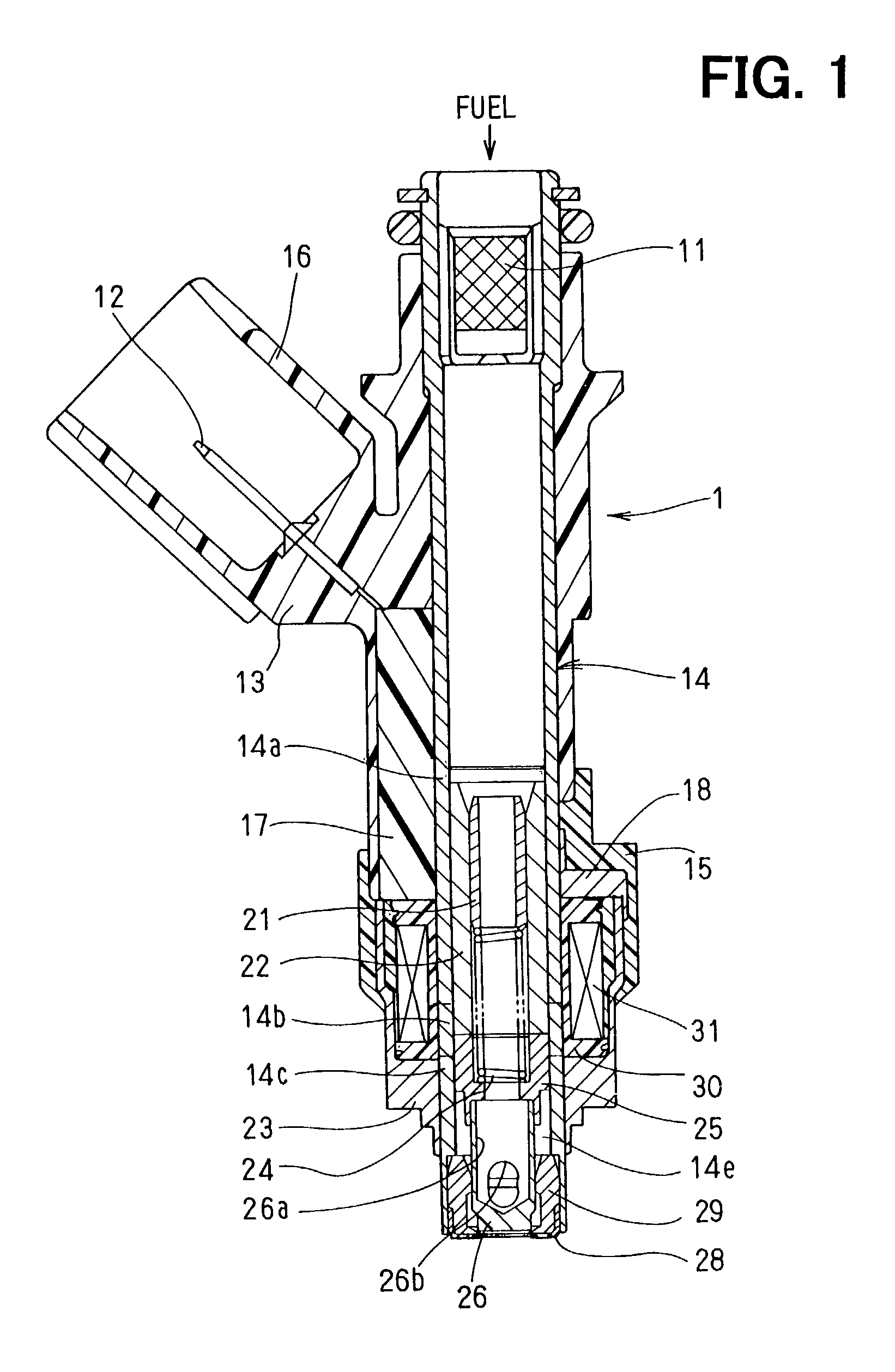
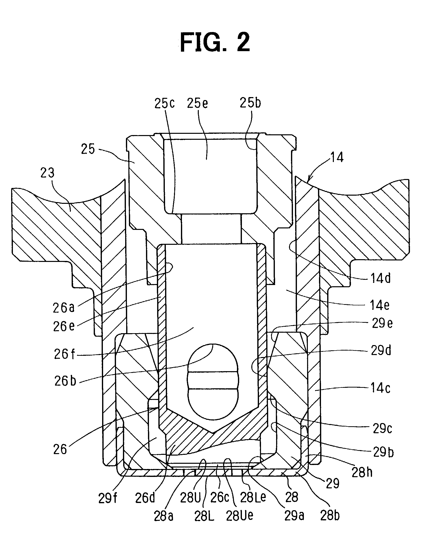
[0053]FIGS. 1 and 2 show a fuel injector according to the present invention. The fuel injector 1 works as a valve for controlling fuel flow and an injector nozzle for injecting, atomizing and metering fuel. The fuel injector 1 supplies fuel into an intake passage of an internal combustion engine such as a spark ignition type gasoline engine.

[0054]Referring to FIGS. 1 and 2, the fuel injector 1 is configured as a cylindrical shape that has a fuel inlet on a top and a fuel outlet on a bottom. The fuel injector 1 has a cylindrical member 14 that extends from the top to the bottom. The cylindrical member 14 has a magnetic portion 14a, nonmagnetic portion 14b and magnetic portion 14c. The nonmagnetic portion 14b is formed by a partial heat treatment. The cylindrical member 14 defines an inner surface 14d and a chamber 14e for accommodating other components. A filter 11 is inserted in the cylindrical member 11.

[0055]Electromagnetic components are disposed on the cylindrical member 14. A c...

second embodiment

[0089]FIG. 11 shows a manufacturing method of the injector nozzle according to the present invention. An adjusting process 220 is performed by a measuring process 223 and the deburring process 210. The measuring process 223 measures a flow rate of one of the orifice member 28 that is already trimmed. The measuring process 223 outputs and feedbacks the measured flow rate to the preceding deburring process 210 in order to adjust a flow rate of another following orifice members 28. At least one of the controllers 30a in the shot blasting processes 211, 212 and 213 inputs the measured flow rate, and corrects the period of time for the shot blasting respectively. For example, if the measured flow rate is smaller than the predetermined flow rate, the controller 30a extends the period of time for the shot blasting. Therefore, the measured flow rate is reflected on the preceding shot blasting process 210 that would be performed on another plate material that has an aperture not yet measured...

fourth embodiment

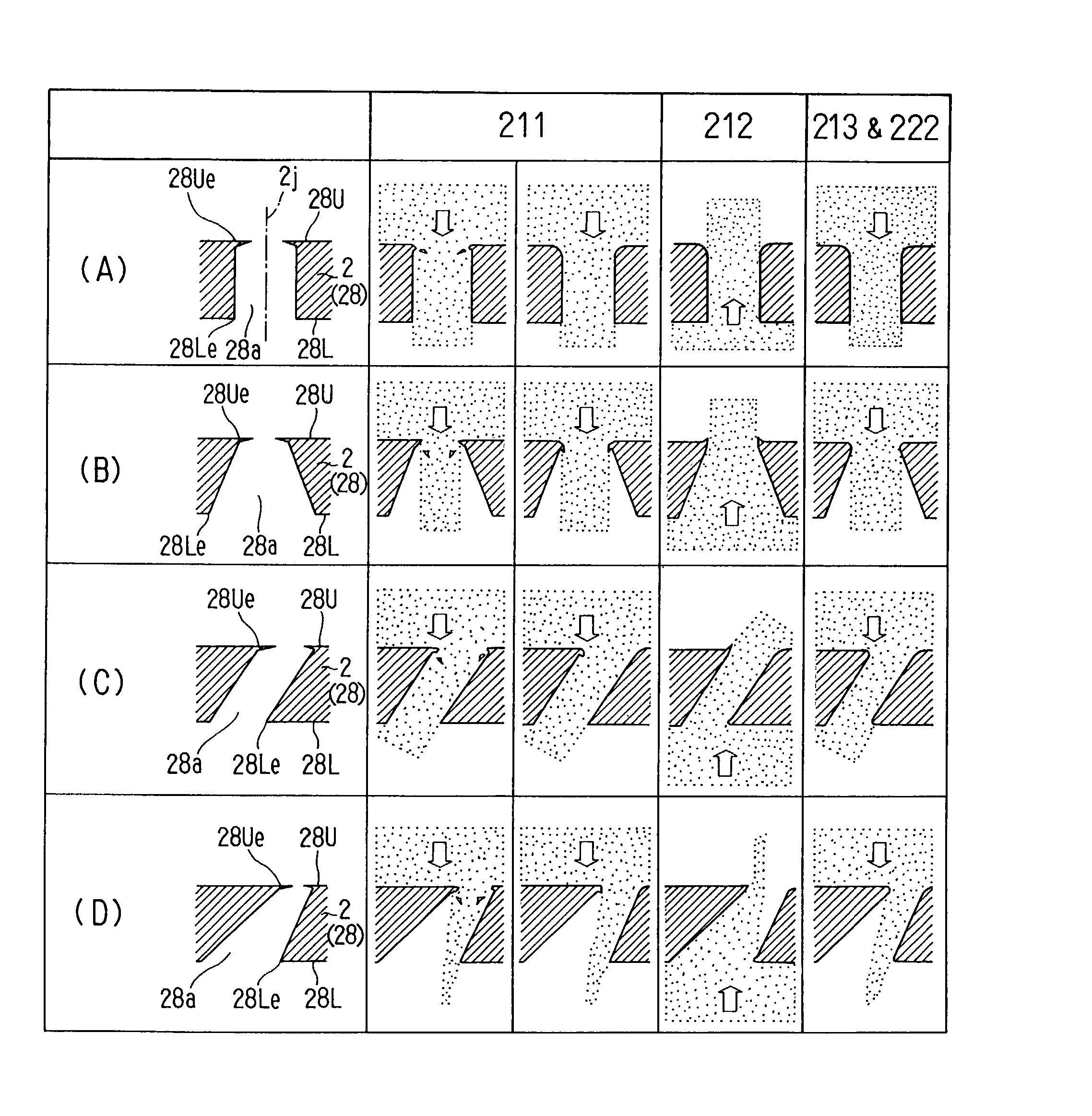
[0093]FIGS. 14A, 14B, 14C and 14D show an edge trimming process of the FIG. 14A shows a beginning of the first shot blasting process 211. As shown in FIG. 14A, the burrs formed on the upper edge 28Ue are removed at a beginning of the first shot blasting process. FIG. 14B shows an end of the first shot blasting process 211. The acute angle edges are deformed in the shot direction. FIG. 14C shows an end of the second shot blasting process 212. The deformations of the acute angle edges are returned and further deformed in the shot direction. FIG. 14D shows the third and fourth shot blasting processes 213 and 222. The edges are trimmed into rounded shapes and are adjusted to permit the target flow rate.

[0094]FIGS. 15 and 16 show a fifth embodiment of the present invention. In this embodiment, an electrical-discharge machining process 100a is carried out instead of the pressing and grinding processes in the first embodiment. FIG. 15 is a cross sectional view showing an electrical-discha...


PUM

PropertyMeasurementUnit
diameteraaaaaaaaaa
sizeaaaaaaaaaa
timeaaaaaaaaaa

Abstract

A fuel injector has an orifice member having an aperture for injecting atomizing and metering fuel. The orifice member is made of a plate material. The orifice member is machined to form the aperture. Then, the orifice member is processed by at least two shot blasting process in opposite directions to remove burrs and trim edges of the aperture. After the process, the orifice plate is inspected by measuring an actual flow rate of the aperture. Then, the orifice plate is processed by a shot blasting process again in accordance with the measured flow rate and a target flow rate.

Description

CROSS REFERENCE TO RELATED APPLICATION[0001]This application is based on Japanese Patent Applications No. 2001-310624 filed on Oct. 5, 2001, No. 2001-310625 filed on Oct. 5, 2001, No. 2002-199898 filed on Jul. 9, 2002 and No. 2002-199899 filed on Jul. 9, 2002 the contents of which are incorporated herein by reference.BACKGROUND OF THE INVENTION[0002]1. Field of the Invention[0003]The present invention relates to an injector nozzle and a manufacturing method of the same.[0004]2. Description of Related Art[0005]An injector nozzle is a device for injecting pressurized fluid through a small hole or aperture. For example, an injector nozzle is used for a fuel injector. In such the application, the fuel injector has an orifice as the small hole, and injects fuel into an intake air passage or a combustion chamber. The orifice defines a flow rate and is a principal part for metering an amount of injected fuel. Therefore, it is important to process the orifice precisely.[0006]JP-A-9-209876 d...

Claims


Application Information

Patent Timeline
Patent Type & Authority Patents(United States)
IPC IPC(8): B21D51/16B23P15/00B24C1/00B24C3/32F02M51/06F02M61/16F02M61/18F02M63/00F02M65/00G05B19/00
CPCB23P15/00B24C1/083B24C3/32F02M51/0682F02M61/168F02M61/1806F02M61/1853F02M65/001G05B19/00B24C1/00Y10T29/49432F02M61/165F02M2200/24F02M2200/505Y10T29/49996Y10T29/479
Inventor MORITA, HIROMICHI
Owner DENSO CORP
Why Eureka
Try Eureka