Surgical apparatus and methods asociated therewith

a surgical apparatus and associated technology, applied in the field of surgical apparatus, can solve the problems of stalling operation, cornea collapse, efficient operation of the system, etc., and achieve the effect of facilitating dynamic adjustmen

Active Publication Date: 2014-08-12
MAASKAMP ARMAND +1
View PDF11 Cites 14 Cited by
  • Summary
  • Abstract
  • Description
  • Claims
  • Application Information

AI Technical Summary

Benefits of technology

[0033]It is, therefore, an object of this invention to provide a surgical apparatus which, when operating in an aspiration mode during a surgical procedure, will respond dynamically to changing fluid-flow conditions within a fluid-flow passage of an aspiration line of the apparatus and facilitate dynamic adjustment of the size of the fluid-flow passage to sustain an established fluid-flow rate within the aspiration line.
[0034]Another object of this invention is to provide a surgical apparatus which, when operating in an aspiration mode during a surgical procedure, will respond dynamically to a surge of fluid flowing within a fluid-flow passage of an aspiration line of the apparatus and dynamically restrict the size of the fluid-flow to establish a desired fluid-flow rate and quickly suppress the surge to prevent potential deleterious effects therefrom.
[0035]A further object of this invention is to provide a surgical apparatus which, during an aspiration mode of operation of a surgical procedure, will respond dynamically to a surge of aspirated fluid flowing within a fluid-flow passage of an aspiration line of the apparatus and dynamically restrict the size of the fluid-flow passage to establish a desired fluid-flow rate and quickly suppress the surge to prevent potential deleterious effects therefrom, and where the surgical apparatus will provide an unrestricted passage within the aspiration line of the apparatus during a reflux mode of operation.
[0036]Still another object of this invention is to provide a surgical apparatus which, during a surgical procedure, will minimize, if not eliminate, the negative effects of air existing within an aspiration line of the surgical apparatus, during the extraction of particles resulting from surgery at a site within a body cavity.
[0040]In addition, this invention contemplates a method of moving fluid through an aspiration line of an aspiration system in either an aspiration direction or a reflux direction during a phacoemulsification procedure for the removal of lens tissue from an eye of a patient, which includes the steps of providing an aspiration line with a fluid flowing therethrough in an aspiration direction at a prescribed rate of flow; providing, in a section of the aspiration line, a facility for adjusting the rate of flow of the fluid in the aspiration direction when a change occurs in the rate of flow from the prescribed rate of flow; and providing facility for reversing the direction of flow of the fluid in a reflux direction through the aspiration line.

Problems solved by technology

A negative pressure within the chamber may cause the cornea to collapse.
In this manner, the presence of air within the aspiration system interferes with the efficient operation of the system, and could stall the operation thereof.
If a large volume of air is present in the system, it is feasible that the required vacuum pressure to sustain a delicate balance between the incoming flow rate of the irrigation fluid to the patient's eye, and the outgoing flow rate of the aspiration fluid and particles from the eye, could be undesirably altered, with catastrophic results to the patient's eye, and inefficient operation of the surgical procedure.
Notwithstanding the purging process, during the aspiration process, troublesome air bubbles may develop within the system, particularly in the cannula, the first aspiration tube, the filter housing, and the juncture connections of these components of the system.
This difference in the diameters is necessitated by the design of a converter with two flow paths and two filters, and presents a potentially unwieldy combination for handling of the hand piece during an aspiration process.
In addition, the air which enters the first flow path prior to the first filter becoming fully wetted, may remain undesirably in the first path as the aspiration process continues.
Also, any air bubbles developed in the fluid subsequent to the fluid passing through the wetted filter, remain with the fluid and cannot be rerouted through the second filter.
The presence of the increased vacuum pressure, when the occlusion breaks free, causes a potentially hazardous surge, or high flow rate, of the aspiration fluid within the aspiration line.
Such a surge of the aspiration fluid can lead to transient aspiration flow rates through the aspiration line that substantially exceed the flow rate of the irrigation fluid into the eye.
The sub-ambient pressure condition may cause (1) an undesirable collapse of the anterior chamber of the eye, (2) undesirable damage to the posterior aspect of the lens capsule of the eye, and / or (3) undesirable movement of endothelium cells, which are critical to normal functions of the cornea, away from the cornea and towards the free-end tip of the cannula.
On the other hand, independent of the formation of the above-noted occlusion, an irrigation-fluid flow rate, which is too high, may also move the endothelium cells away from the cornea, or undesirably cause the cells to be aspirated out of the eye.
Even if the restricted opening is as fully open as possible, the restriction imposed by the fully-open restrictive opening will not facilitate the development of the force necessary to break free the occlusion.

Method used


Image

  • Surgical apparatus and methods asociated therewith
  • Surgical apparatus and methods asociated therewith
  • Surgical apparatus and methods asociated therewith

Examples


Embodiment Construction

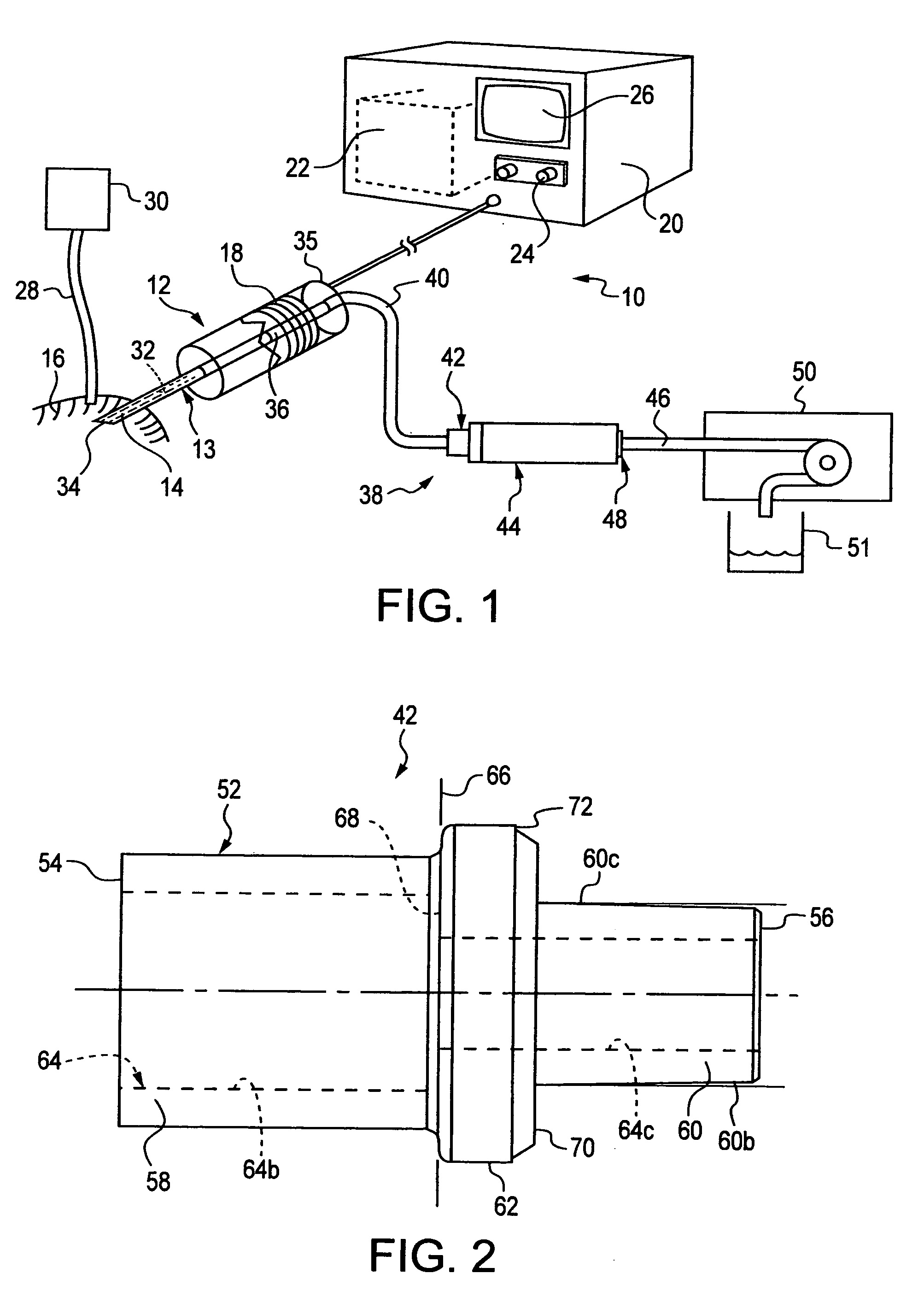
[0055]A surgical apparatus 10, as illustrated in FIG. 1, includes a hand piece 12, containing a needle-like, hollow cannula 13, which is formed with a free-end cannula tip 14 that extends from a forward end 15 of the hand piece. During a surgical procedure, the free-end tip 14 can be inserted into a cornea 16 of a patient's eye, through a small incision formed by the surgeon in the cornea. The hand piece 12 also contains one or more ultrasonic transducers 18 that convert electrical power into mechanical movement to ultrasonically drive the hollow cannula 13 and the tip 14. The hand piece 12 is typically held by a surgeon who performs the surgical procedure, such as, for example, a phacoemulsification procedure (hereinafter “the phaco procedure”), to break a lens, located within the cornea 16 and an anterior chamber of the eye, into particles and residual debris (hereinafter “the particles”).

[0056]The hand piece 12 is connected to a console 20 of the surgical apparatus 10, which incl...


PUM


Abstract

A surgical apparatus 10, used in a phaco procedure, includes a filter assembly 44 / 44a for near, or complete, elimination of air bubbles in an aspiration line of an aspiration system 38. The apparatus 10 includes a suppressor 110, which, during an aspiration mode of operation, maintains a fluid flow rate at 50 cc / min, and, upon an occlusion breaking free, dynamically decreases the fluid flow rate from a high surge rate to the rate at 50 cc / min. The apparatus 10 includes facility for operating in a reflux mode to direct unrestricted fluid flow through the aspiration line of the aspiration system 38.

Description

[0001]This application claims the benefit of U.S. Provisional Application No. 61 / 217,809, filed on Jun. 4, 2009, and U.S. Provisional Application No. 61 / 275,735, filed on Sep. 2, 2009, both of which are incorporated herein by reference thereto.FIELD OF THE INVENTION[0002]This invention relates to surgical apparatus and to methods associated therewith, and, in particular, relates to surgical apparatus, which includes an aspiration system, having a filter assembly and a dynamic surge suppressor, for use in surgical procedures, and further relates to methods associated with such surgical apparatus.BACKGROUND OF THE INVENTION[0003]It has been disclosed in the past, at least to a limited extent, that in certain surgical procedures conducted within a body cavity, such as, for example, a phacoemulsification procedure, a lens capsule, located in an anterior chamber of a human eye, is broken into particles and residual debris (all hereinafter referred to as “the particles”), must be continuo...

Claims


Application Information

Patent Timeline
Patent Type & Authority Patents(United States)
IPC IPC(8): A61M1/00
CPCA61M1/0031A61F9/00745A61M1/74
Inventor MAASKAMP, ARMANDURICH, ALEX
Owner MAASKAMP ARMAND
Why Eureka
Try Eureka