Artificial potential field method for automatic driving vehicle decision-making layer path planning

A technology of artificial potential field and path planning, which is applied to vehicle components, input parameters of external conditions, control devices, etc., can solve the problem that the vehicle cannot reach the end point, and achieve the effect of low energy consumption

Inactive Publication Date: 2020-11-03
北京理工大学重庆创新中心 +1
View PDF5 Cites 9 Cited by
  • Summary
  • Abstract
  • Description
  • Claims
  • Application Information

AI Technical Summary

Problems solved by technology

Since the artificial potential field method used in the current path planning mostly uses the potential field to directly generate attractive or repulsive force as t

Method used


Image

  • Artificial potential field method for automatic driving vehicle decision-making layer path planning
  • Artificial potential field method for automatic driving vehicle decision-making layer path planning

Examples


Embodiment 1

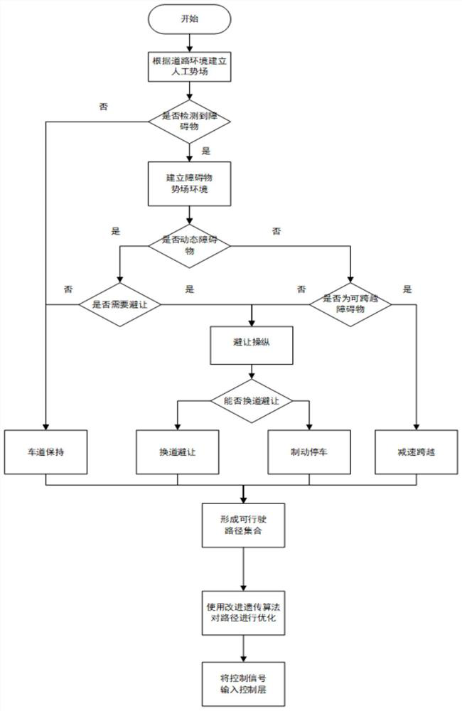
[0022] The vehicle travels straight along the lane, and the road environment is established so that the vehicle cannot drive beyond the lane boundary. And there is a speed bump ahead to remind the driver to slow down. At this time, the perception layer transmits the information to the decision-making layer to judge that there is no need to change lanes at this time, and the decision-making layer establishes a potential field so that the value of the potential field on both sides of the road is high enough that vehicles cannot cross. And as the vehicle gradually approaches the deceleration belt ahead, the potential field value gradually increases to decelerate the vehicle, and when the deceleration reaches a certain level, the potential field gradient decreases to allow the vehicle to pass smoothly.

Embodiment 2

[0024] A pedestrian suddenly appeared in front of the vehicle. The perception layer transmits the position of the obstacle to the decision-making layer, judges that the lane change distance is exceeded, and quickly establishes a potential field. As the longitudinal distance between the vehicle and the pedestrian in front decreases, the value of the potential field increases rapidly. And when it is close enough to pedestrians, the potential field value increases to infinity, so that the vehicle brakes to ensure the safety of pedestrians.

Embodiment 3

[0026] The vehicle is traveling at a speed of 30km / h, and the vehicle 100m ahead is traveling at a speed of 25km / h. The perception layer transmits the position and speed of the vehicle in front of the obstacle to the decision-making layer. By judging the longitudinal distance between the obstacle and the vehicle, the lane change operation can be performed. The value of the potential field near the obstacle is increased through the artificial potential field, so that the vehicle cannot be too close Obstacles, so that the vehicle double-lane shifting condition can be safely carried out.

[0027] Comparison with traditional potential field methods:

[0028] The traditional artificial potential field path planning algorithm only performs path planning based on state information such as obstacle position and velocity, and is mostly used in the field of robotics. One of the existing methods, Zheng Jifa. A path planning method based on the artificial potential field method: China, 1...


PUM


Abstract

The invention provides an artificial potential field method for automatic driving vehicle decision-making layer path planning, and the method comprises the steps: S1, building a road environment through an artificial potential field method, and enabling a vehicle to drive in a road boundary; S2, acquiring surrounding information through a vehicle sensing device, and establishing different potential field functions for different types of obstacles, so the vehicle has different processing modes for different obstacles; S3, planning a set of safety paths according to the established potential field environment, and optimizing by using an improved genetic algorithm to find the shortest path. According to the method, the driving environment of an automatic driving vehicle is established by using an artificial potential field method, so that the vehicle performs different driving operations on different types of obstacles, and the improved genetic algorithm is used for optimizing the path, so that the vehicle is driven safely, and the energy consumption is minimum.

Description

technical field [0001] The invention relates to the technical field of automatic driving vehicles, in particular to an artificial potential field method for path planning of decision-making layers of automatic driving vehicles. Background technique [0002] The self-driving vehicle plans the vehicle's driving path through the surrounding environment information obtained by the perception layer, so that the vehicle can drive safely and smoothly. Since the artificial potential field method used in the current path planning mostly uses the potential field to directly generate attractive or repulsive force as the external force of the vehicle to drive the intelligent vehicle to move, local minimum values ​​are prone to appear so that the vehicle cannot reach the destination. In this paper, to solve this problem, the artificial potential field method is improved, and the path is optimized by combining the genetic algorithm, considering the vehicle dynamics constraints and driving...

Claims


Application Information

Patent Timeline
IPC IPC(8): B60W30/09B60W30/095B60W50/00B60W60/00B60W10/18B60W10/20
CPCB60W10/18B60W10/20B60W30/09B60W30/0956B60W50/0098B60W2050/0043B60W2710/18B60W2710/20B60W60/0015B60W60/0027B60W2552/50B60W2554/80
Inventor 杨超王伟达刘文婕徐彬王暮遥路深赵靖张宇航
Owner 北京理工大学重庆创新中心
Why Eureka
Try Eureka